


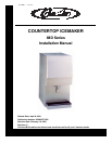

Countertop Icemaker IMD Series Installation Manual
Publication Number: 638085277INS - 4 - © 2004-2009, IMI Cornelius Inc.
INSTALLATION INSTRUCTIONS
REMOVE ICEMAKER FROM CARTON
1. Keep unit in the upright position, remove carton and pallet from unit and inspect unit for damage.
Upon inspection of unit, if any damage is found, file a claim with carrier immediately.
2. Locate Startup Card either on outside of container or on plastic liner. Fill in proper information and
send one copy to factory, and other copy to Distributor. Postage is prepaid.
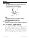
CABINET REMOVAL
1. Locate and remove the (2) screws from under the front cover. Lift cover forward and up to remove.
2. Lift up front edge of top cover. Slide back about 1/2 inch and remove.
3. Remove (6) screws from the front of the machine.
4. Remove side panels by sliding the front edge out and then back slightly to disengage.
5. Remove the front splash panel by lifting slightly to disengage the front, then tilt forward and remove.
6. Remove bin top and remove shipping insert.
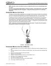
PREPARATION OF INSTALLATION SITE
1. The refrigeration system on air cooled units requires airflow, so a well ventilated area should be
chosen. A minimum of (6) inches must be maintained, free of any obstruction, for air intake. A min-
imum of (4) inches clearance is required of air exhaust.
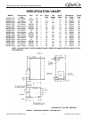
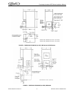
2. With template provided make the necessary provisions in the counter for water, drain and the elec-
trical hook-up. Provisions are available for rear and bottom connections of water and electrical.
Use hole plugs provided to plug unused holes.
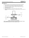
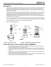
WATER INLET HOOK-UP
1. Water Inlet - Fitting is a 1/4” SAE male flare located at the rear of the unit. Connect water supply
with a 1/4” or larger copper or flexible tubing.
2. Water Pressure - Unless otherwise specified, the unit is designed to operate on water pressures
between 10 P.S.I. and 90 P.S.I. (NOTE: for pressures above 90 P.S.I. a regulator must be installed).
3. Water Cooled Condensers
A. Inlet to modulating valve uses 3/8” FPT. Use separate 3/8” or larger water line.
B. Outlet is 3/8” FPT.
4. Filter Conditioner are recommended on supply lines to icemakers. Never run the water supply to
water cooled Condenser through Filter/Conditioner, it uses up the cartridge unnecessarily and a
saturated cartridge can starve the icemaker causing premature component damage. Separate
water supplies are recommended.
NOTE: Unit must be installed per local plumbing code.
ELECTRICAL SUPPLY
1. Power Access - Is provided by way of a 7/8” dia. hole in both the base and the rear panel. Route
incoming power in conduit, to icemaker electrical control box. Make connections to wires provided
in control box and ground lug/screw. Plug unused hole.
2. Fused Line - Should be a dedicated circuit checked and sized according to electrical rating shown
on unit nameplate.
NOTE: Unit must be installed per local electrical code.