


Connecting Appliance To Electricity Connecting Appliance To Gas Supply
Electrical Wiring Information A TRAINED SERVICEMAN OR GAS APPLIANC
INSTALLER MUST MAKE THE GAS SUPP[
The neutral of this unit is grounded to the frame through the CONNECTION. Leak testing of the appliance shall t
green grounding wire. If local conditions do not permit conducted by the installer according to the instructior
grounding of the neutral, untwist or disconnect the green wire given.
and connect the green wire to ground in accordance with local
codes. Connect the white neutral to the service neutral. 1. Install a manual shut-off valve in an accessible location
the gas line external to this appliance for the purpose
Proper Electric Supply shutting off gas supply to this appliance.
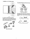
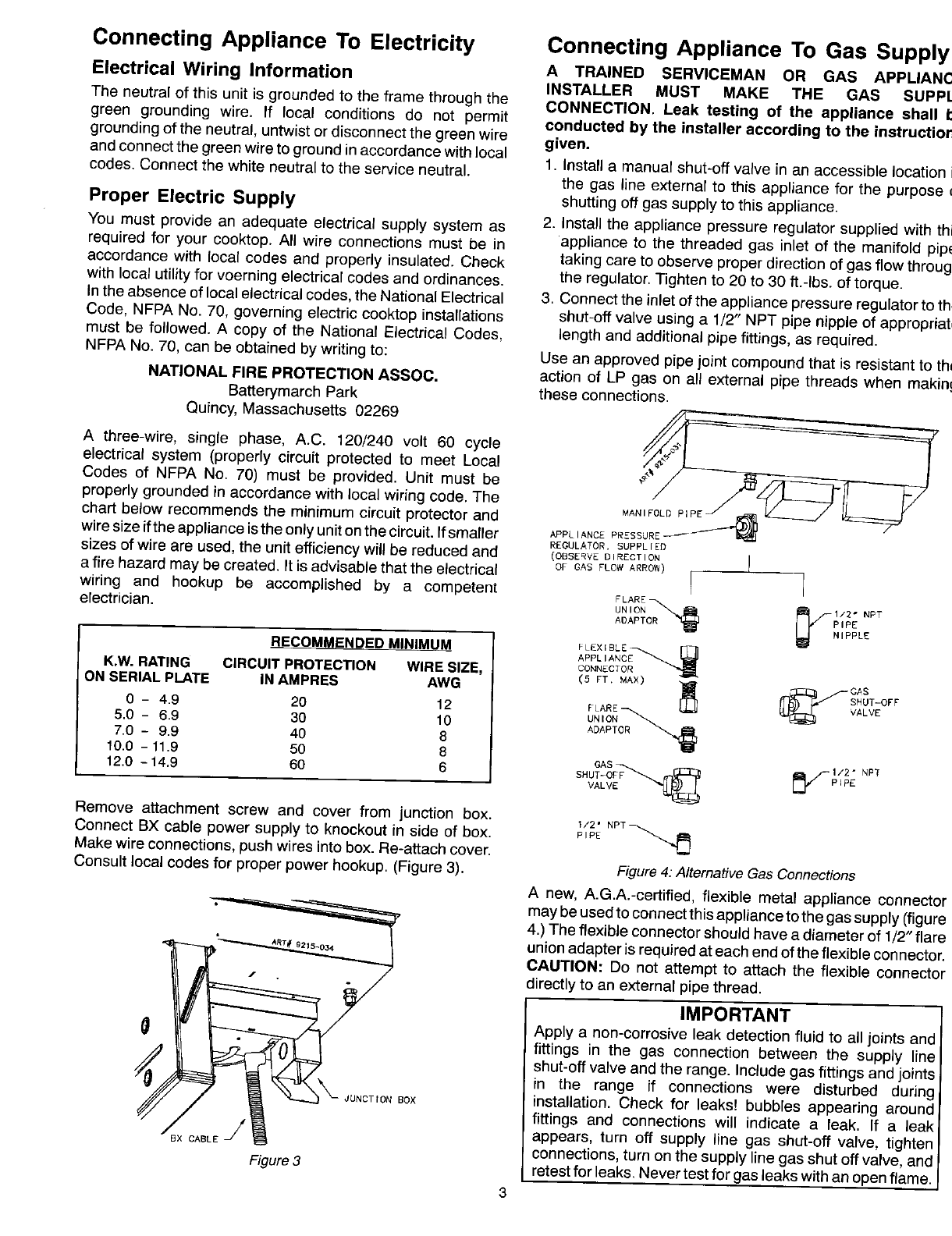
2. Install the appliance pressure regulator supplied with th
You must provide an adequate electrical supply system as
required for your cooktop. All wire connections must be in appliance to the threaded gas inlet of the manifold pip(
accordance with local codes and properly insulated. Check taking care to observe proper direction of gas flow throug
with local utility for voerning electrical codes and ordinances, the regulator. Tighten to 20 to 30 ft.-Ibs, of torque.
In the absence of local electrical codes, the National Electrical 3. Connect the inlet of the appliance pressure regulator to th
Code, NFPA No. 70, governing electric cooktop installations shut-off valve using a 1/2" NPT pipe nipple of appropriat
must be followed. A copy of the National Electrical Codes, length and additional pipe fittings, as required.
NFPA No. 70, can be obtained by writing to: Use an approved pipe joint compound that is resistant to th
NATIONAL FIRE PROTECTION ASSOC. action of LP gas on all external pipe threads when makin
Batterymarch Park these connections.
Quincy, Massachusetts 02269 R______
A three-wire, single phase, A.C. 120/240 volt 60 cycle
electrical system (properly circuit protected to meet Local
Codes of NFPA No. 70) must be provided. Unit must be
properly grounded in accordance with local wiring code. The
chart below recommends the minimum circuit protector and
wire size ifthe appliance isthe only unit on the circuit. If smaller APPL_A,CEP
REGULATOR, SUPPL IEO
sizes of wire are used, the unit efficiency will be reduced and (OBSErvEDIRECTION
a fire hazard may be created. It is advisable that the electrical OFGASFLOWARROW)I } I
wiring and hookup be accomplished by a competent I I
FLARED_
electrician. UNmN _2" ,_T
ADAPT PIPE
HI PPLE
RECOMMENDEDMINIMUM _LEXIBLE.--_.f_
APPLIANCE
K.W.RATING CIRCUIT PROTECTION WIRESIZE, CONNgCTO
ONSERIAL PLATE IN AMPRES AWG (5 FT. MAX) _- ___ _--GAS
SHUT-OFF
0- 4.9 20 12 FLARE _ VALVE
UN IONoR-_ _
5.0- 6.9 30 10 ADAPT
7.0- 9.9 40 8
10.0 - 11.9 50 8
12.0 - 14.9 60 6 GASF_._ __ _1"/--1/2" NPT
SHUT-OFF PI PE
VALV
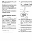
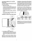
Remove attachmentscrew and cover from junctionbox.
1/2" NPT_
Connect BX cable power supply to knockout in side of box. P_PE
Make wire connections, push wires into box. Re-attach cover.
Consult local codes for proper power hookup. (Figure 3). Figure4:Alternative GasConnections
A new, A.G.A.-certified, flexible metal appliance connector
.__ may be used to connect this appliance tothe gas supply (figure
4.) The flexible connector should have a diameter of 1/2" flare
._ " union adapter is required at each end of the flexible connector.
CAUTION: Do not attempt to attach the flexible connector
t_ ,_/ directly to an external pipe thread.
IMPORTANT
(_ Apply a non-corrosive leak detection fluid to all joints and
fittings in the gas connection between the supply line
shut-off valve and the range. Include gas fittings and joints
in the range if connections were disturbed during
Box installation. Check for leaks! bubbles appearing aroundfittings and connections will indicate a leak. If a leak
j/ appears, turn off supply line gas shut-off valve,
4×
tighten
CABLE
connections, turn on the supply line gas shut offvalve, and
F lure3 retestfor leaks, Never testforgas leaks withan openflame.
3