


To Convert Appliance For Use With Installation of Natural Gas Orifice Spuds
Natural Gas This appliance is equipped for electronic auto-reignition by
Ifthis appliance has been converted for use with LP gas, each means ofa spark igniter located at the side ofeach burner. The
of the following modifications must be performed to convert burners are designed to light at any valve rotation that admits
the unit back to natural gas. sufficient gas flow to support a flame and to automatically
re-light following a momentary loss of flame due to a draft or
A. Replace all orifice spuds other adverse condition. This feature is provided as a
Perform Steps 1 through 4 on page 4. convenience and is not intended as a safety feature.
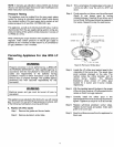
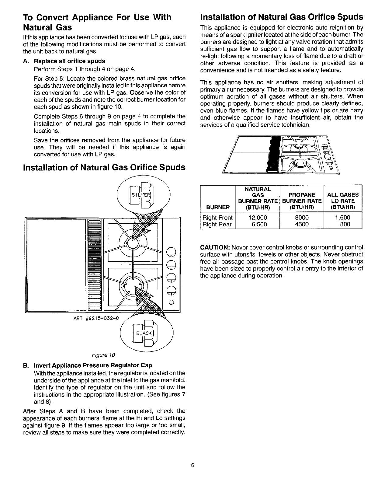
For Step 5: Locate the colored brass natural gas orifice
spudsthatwereoriginallyinstalledinthisappliancebefore This appliance has no air shutters, making adjustment of
its conversion for use with LP gas. Observe the color of primary air unnecessary. The burners are designed to provide
each of the spuds and note the correct burner location for optimum aeration of all gases without air shutters. When
each spud as shown in figure 10. operating properly, burners should produce clearly defined,
even blue flames. If the flames have yellow tips or are hazy
Complete Steps 6 through 9 on page 4 to complete the and otherwise appear to have insufficient air, obtain the
installation of natural gas main spuds in their correct services of a qualified service technician.
locations.
Save the orifices removed from the appliance for future / ___
use. They will be needed if this appliance is again
converted for use with LP gas.
Installation of Natural Gas Orifice Spuds
NATURAL
GAS PROPANE ALL GASES
BURNER RATE BURNERRATE LO RATE
BURNER (BTU/HR) (BTU/HR) (BTU/HR)
Right Front 12,000 8000 1,600
Right Rear 6,500 4500 800
Q CAUTION: Never cover control knobs or surrounding control
surface with utensils, towels or other objects. Never obstruct
Q free air passage past the control knobs. The knob openings
have been sized to properly control air entry to the interior of
Q the appliance during operation.
Q
©
ART #9215-032-0
Figure 10
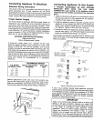
B. Invert Appliance Pressure Regulator Cap
With the appliance installed, the regulator is located on the
underside ofthe appliance at the inlet to the gas manifold.
Identify the type of regulator on the unit and follow the
instructions in the appropriate illustration. (See figures 7
and 8).
After Steps A and B have been completed, check the
appearance of each burners' flame at the Hi and Lo settings
against figure 9. If the flames appear too large or too small,
review all steps to make sure they were completed correctly.