


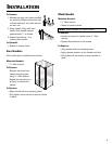
INSTALLATION
Connecting the Water Supply
(select models)
To avoid pr
operty damage or possible injury,
follow basic precautions, including the
following:
• Consult a plumber to connect
1
⁄4” O.D. copper
tubing
to household plumbing to assure
compliance with loc
al codes and ordinances.
• Confirm water pressure to water valve is between
35 and 100 pounds per square inch, 20 pounds
per square inch without filter
.
•
Do not use a self-piercing, or
3
⁄16” saddle valve.
Both reduce water flow c
an become clogged over
time, and may cause leaks if repair is attempted.
• Wait two to three hours before placing refrigerator
into final position to check and correct any water
leaks. Recheck for leaks after 24 hours.
• Verify the copper tubing under the sleeve is
smooth and free from defect
s.
Do not reuse an
old sleeve.
CAUTION
To reduce risk of injury or death, follow basic
precautions, including the following:
• Read all instructions before installing ice maker.
•
Do not attempt installation if instructions are not
understood or if they are beyond personal skill
level.
• Observe all local codes and ordinances.
•
Do not service ice maker unless specifically
recommended in Use & Care Guide or published
user-repair instructions.
• Disconnect power to refrigerator
before installing
ice maker.
• Water damage due to an improper water
connection may c
ause mold/mildew growth. Clean
up spills or leakage immediately
.
WARNING
6
Materials Needed
•
1
⁄4” outer diameter flexible copper tubing
• Shut-off valve (requires a
1
⁄4” hole to be drilled into
water supply line before valve att
achment)
• Adjustable wrench (2)
•
1
⁄4” hex nut driver
Notes:
• Use copper tubing only for installation. Plastic is
less durable and can cause damage.
• Add 8’ to tubing length needed to reach water
supply for creation of service loop.
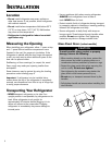
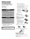
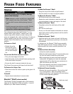
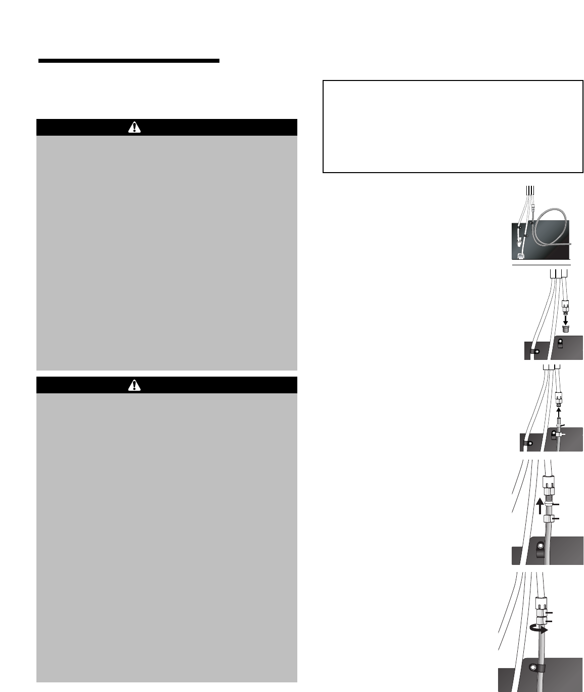
1. Create service loop with
copper tubing (minimum 2’
diameter). Avoid kinks in the
copper tubing when bending
the service loop.
Do not use
plastic tubing.
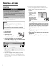
2. Remove plastic cap from water valve
inlet por
t.
2’ diameter
minimum
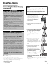
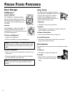
3.
Place brass nut
(A) and sleeve (B)
on copper tube end as illustrated.
Reminder:
Do not
use an old
sleeve. The nut and sleeve are
provided in the Use and Care
packet.
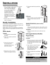
5. Slide brass nut over sleeve and
screw nut into inlet port.
Place adjustable wrench on nut
(1) attached to plastic waterline
and maintain position.
Using second adjust
able wrench,
turn the lower nut
(2)
counterclockwise and fully
tighten while holding the upper
nut in place.
Important: Do not over-tighten. Cross threading
may occur.
4.
Place end of copper tubing into
water valve inlet port. Shape
tubing slightly -
Do not kink – so
that tubing feeds straight into inlet
por
t.
A
B
A
B
1
2
Cont.