


18
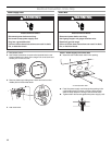
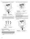
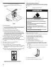
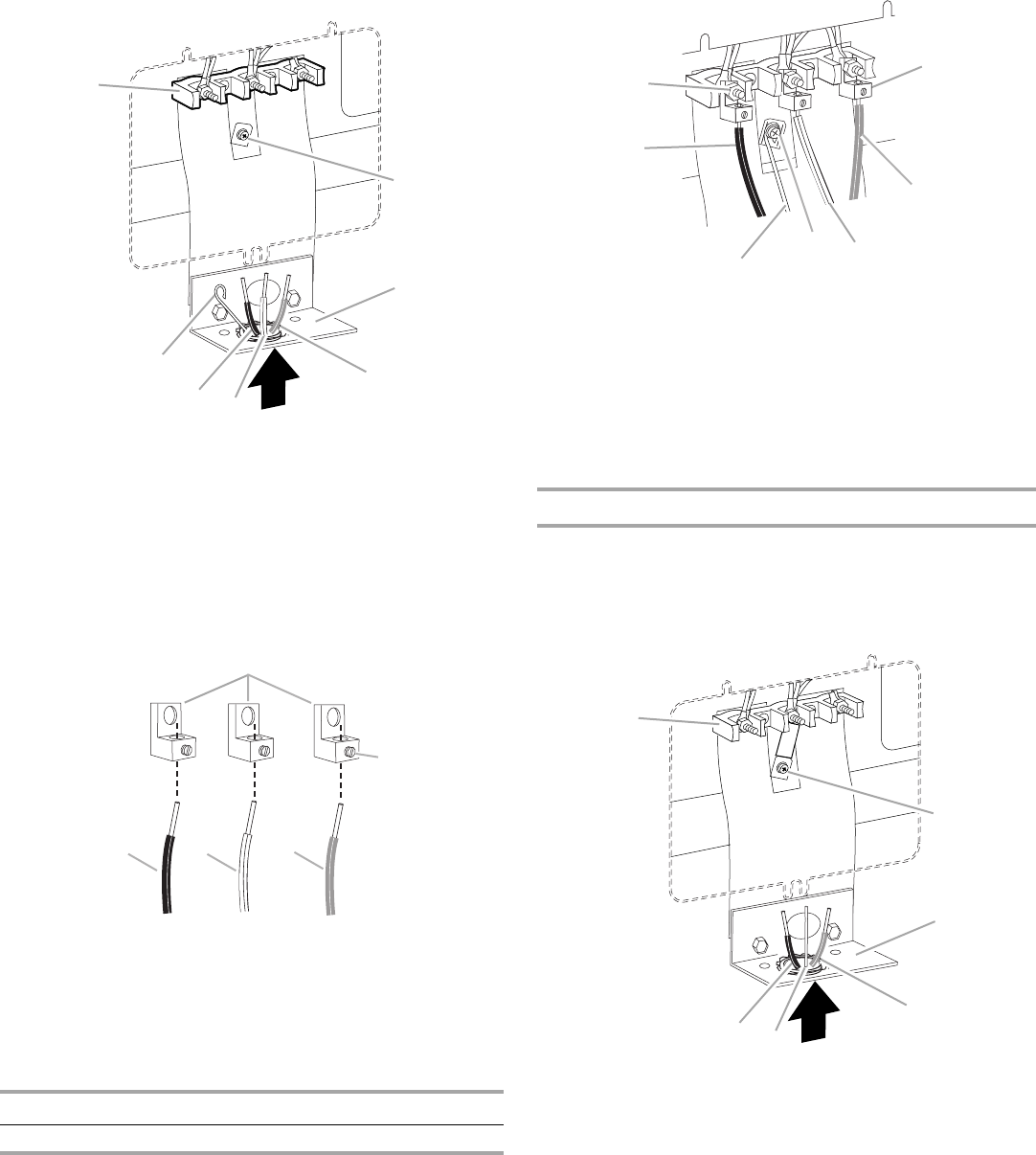
3. Pull the conduit through the strain relief on cord/conduit plate
on bottom of range. Allow enough slack to easily attach
wiring to the terminal block.
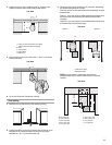
4. Attach terminal lugs to line 1 (black), neutral (white), and line 2
(red) wires. Loosen (do not remove) the setscrew on the front
of the terminal lug and insert exposed wire end through
bottom of terminal lugs. Securely tighten set screw to torque
as shown in the following Bare Wire Torque Specifications
chart.
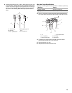
Bare Wire Torque Specifications
Attaching terminal lugs to the terminal block - 20 lbs-in. (2.3 N-m)
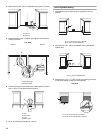
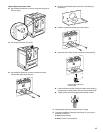
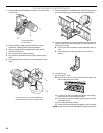
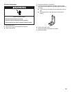
5. Use Phillips screwdriver to connect the bare (green) ground
wire to the range with the ground-link screw. The ground wire
must be attached first and must not contact any other
terminal.
6. Use ³⁄₈" nut driver to connect the neutral (white) wire to the
center terminal block post with one of the 10–32 hex nuts.
7. Connect line 1 (black) and line 2 (red) wires to the outer
terminal block posts with 10-32 hex nuts.
8. Securely tighten hex nuts.
9. Replace terminal block access cover.
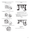
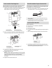
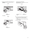
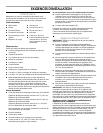
3-wire connection: Direct Wire
Use this method only if local codes permit connecting ground
conductor to neutral supply wire.
1. Pull the conduit through the hole and conduit plate on bottom
of range. Allow enough slack to easily attach the wiring to the
terminal block.
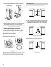
A.Terminal block
B.Ground-link screw
C.Cord/conduit plate
D.Line 2 (red) wire
E.Neutral (white) wire
F. Line 1 (black) wire
G.Bare (green) ground wire
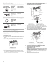
A.Terminal lug
B.Setscrew
C.Line 1 (black) wire
D.Neutral (white) wire
E.Line 2 (red) wire
Wire Awg Torque
8 gauge copper 25 lbs-in. (2.8 N-m)
6 gauge aluminum 35 lbs-in. (4.0 N-m)
A
B
C
D
E
F
G
A
B
C
DE
A.10–32 hex nut
B.Line 1 (black)
C.Bare (green) ground wire
D.Ground-link screw
E.Neutral (white) wire
F. Line 2 (red)
G.Terminal lug
A.Terminal block
B.Ground-link screw
C.Cord/conduit plate
D.Line 2 (red) wire
E.Bare (green) ground wire
F. Line 1 (black) wire
B
A
G
E
C
D
F
A
B
C
D
E
F