


3
INSTALLATION REQUIREMENTS
Tools and Parts
Gather the required tools and parts before starting installation.
Read and follow the instructions provided with any tools listed
here.
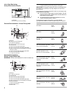
Tools needed
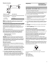
Parts supplied
Check that all parts are included.
■ 3 - #10-32 hex nuts (attached to terminal block)
■ 3 - Terminal lugs
■ 2 or 3 - Oven racks (depending on your model)
■ Blower motor
■ 2 - vent clamps
■ Flexible vent
■ Flow tester card
■ Blower location template
■ 4 - #8 x ¾" screws (for mounting blower motor bracket)
■ 2 - #12 x 1⁵⁄₈" screws (for mounting anti-tip bracket)
■ Anti-tip bracket (taped to package containing literature in
oven cavity)
Anti-tip bracket must be securely mounted to back wall or
floor. Thickness of floor may require longer screws to anchor
bracket to subfloor. Longer screws are available from your
local hardware store.
Parts needed
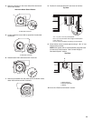
■ One of the following Jenn-Air wall caps:
Jenn-Air
®
5" (12.7 cm) Round Surface Wall Cap Damper.
Order Part Number A405.
Jenn-Air
®
6" (15.2 cm) Round Surface Wall Cap Damper.
Order Part Number A406.
Jenn-Air
®
3¼" x 10" (8.3 x 25.4 cm) Surface Wall Cap
Damper. Order Part Number A403.
To order, see the “Assistance or Service” section of the Use
and Care Guide.
■ Metal ducting
■ Vent clamps
■ Concrete anchors (for concrete floor mounting)
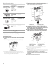
■ 2 - 2" x 4" x 8¾" (5.0 x 10.2 x 22.2 cm) wood spacers (for left
or right side venting)
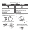
If using a power supply cord:
■ A UL listed power supply cord kit marked for use with ranges.
The cord should be rated at 250 volts minimum, 40 amps or
50 amps that is marked for use with nominal 1³⁄₈" (3.5 cm)
diameter connection opening and must end in ring terminals
or open-end spade terminals with upturned ends.
■ A UL listed strain relief.
Check local codes. Check existing electrical supply. See
“Electrical Requirements” section.
It is recommended that all electrical connections be made by a
licensed, qualified electrical installer.
Location Requirements
IMPORTANT: Observe all governing codes and ordinances.
■ It is the installer’s responsibility to comply with installation
clearances specified on the model/serial rating plate. The
model/serial rating plate is located on the right-hand side of
the oven frame behind the storage drawer panel.
■ The range should be located for convenient use in the
kitchen.
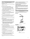
■ To eliminate the risk of burns or fire by reaching over heated
surface units, cabinet storage space located above the
surface units should be avoided. If cabinet storage is to be
provided, the risk can be reduced by installing a range hood
that projects horizontally a minimum of 5" (12.7 cm) beyond
the bottom of the cabinets.
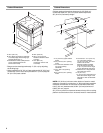
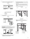
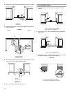
■ Cabinet opening dimensions that are shown must be used.
Given dimensions are minimum clearances.
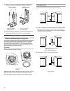
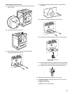
■ The floor anti-tip bracket must be installed. To install the anti-
tip bracket shipped with the range, see “Install Anti-Tip
Bracket” section.
■ Grounded electrical supply is required. See “Electrical
Requirements” section.
IMPORTANT: To avoid damage to your cabinets, check with your
builder or cabinet supplier to make sure that the materials used
will not discolor, delaminate or sustain other damage. This oven
has been designed in accordance with the requirements of UL
and CSA International and complies with the maximum allowable
wood cabinet temperatures of 194°F (90°C).
Mobile Home - Additional Installation Requirements
The installation of this range must conform to the Manufactured
Home Construction and Safety Standard, Title 24 CFR, Part 3280
(formerly the Federal Standard for Mobile Home Construction
and Safety, Title 24, HUD Part 280). When such standard is not
applicable, the Standard for Manufactured Home Installations,
ANSI A225.1/NFPA 501A or with local codes.
Mobile home installations require:
■ When this range is installed in a mobile home, it must be
secured to the floor during transit. Any method of securing
the range is adequate as long as it conforms to the standards
listed above.
■ Four-wire power supply cord or cable must be used in a
mobile home installation. The appliance wiring will need to be
revised. See “Electrical Connection” section.
■ Tape measure
■ Level
■ Phillips screwdriver
■ Flat-blade screwdriver
■ Saber or keyhole saw
■ Marker or pencil
■ Wrench or pliers
■ ⁵⁄₁₆" nut driver
■ ¼" nut driver
■ Drill
■ ¹⁄₈" (3.2 mm) drill bit
■ ³⁄₁₆" (4.8 mm) carbide-tipped
masonry drill bit (for concrete/
ceramic floors)