


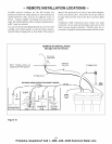

- CARE OF YOUR REVERSE OSMOSIS SYSTEM -
TUBING CONNECTION
(all push- in fitting locations)
This RO system includes push-in fittings for quick
tubing connection at most locations. If working with
the fittings, do the following.
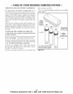
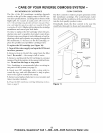
Connection (Figure 12):
1. Use a sharp cutter or knife to cut the end of tubing
square.
2. Inspect the end (about 1") of the tubing to be sure
there are no nicks, scratches or other rough spots. If
needed, cut the tubing again.
3. Push tubing through the collet and all the way into
fitting. Full engagement is 11/16" for 1/4" tubing,
and 3/4" for 3/8" tubing.
If using tubing other than tubing supplied with the
system, be sure it is of high quality, exact size and
roundness with a smooth surface.
Tubing correctly cut and connected
cut tubing s_uare
I I
I
end of tubing round and
smooth, with no cuts,
nicks or fiat spots
collet .__
_ 11/16" (1/4" tubing)
' engagement
Fg=- 3/4" (3/8" tubing)
Figure 12
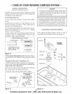
To Disconnect Tubing (Figure 13): Push the collet in-
ward and hold with a finger while pulling the tubing
out.
Changing Collet and O-ring (Figure 13):
1. With a small screwdriver remove the collet and o-
ring from the fitting. Be careful not to scratch the in-
ternal walls of the collet port.
2. Be sure the port is clean, then lubricate and insert
the o-ring seal to the bottom of the port.
3. Push the collet inward until it locks in place.
collet (depress to
remove tubing)
tubi_._
/
Replacing collet and
o-ring seal
Push o-ring seal into
bottom of port, then
follow with collet.
_--_fitting
collet
! m 1
I CAUTION I
I DO NOT USE VINEGAR OR OTHER ACID BASED I
I CLEANERS ON THIS RO SYSTEM. THEY WILL I
I DEGRADE SOME RO SYSTEM PARTS. ALWAYS I
I USE SOAP ANDWATER. I
I m m.I
I This reverse osmosis system contains a replaceable I
treatment component critical to the efficiency of the
I system. Replacement of the reverse osmosis compo- I
I nent should be with one of identical specifications, I
I as defined by the manufacturer; to assure the same I
I efficiency and contaminant reduction performance. I
I _ m.I
AUTOMATIC SHUTOFF SERVICE
If the shutoff assembly requires service, be sure to
reassemble parts exactly as shown in Figure 14.
screw (4)
SHUTOFF
ASSEMBLY
diaphragm
plunger
spacer ring
o-ring
spring
ball
check
valve
diaphragm
Figure 13 Figure 14
14
Problems, Questions? Call 1-800-426-9345 Kenmore Water Line