


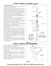

STEP 3: INSTALL FAUCET (cont.)-
B. ASSEMBLE FAUCET
NOTE: If the faucet and spout are unassembled, slide
the spout into the faucet body.
1. Snap LED assembly into electronics ring (may al-
ready be assembled) and o-ring in the groove on the
bottom of the ring and slide the chrome monitor ring
onto the faucet stud. The monitor ring LED wire must
be routed through the sink or countertop hole and
through the spacel; if spacer is used, (Figure 6).
NOTE: If you route the RO drain tubing directly to the
drain point, disregard steps 2 and 4 below and follow
directions on page 17.
2. Take the 30" length of 3 / 8" black tubing and push one
end onto the 3/8" faucet barb fitting (Figure 6).
3. Move the RO system into position, under the sink.
(Referring to page 7, hang the system on cabinet wall,
or lay on the floor surface, as desired.)
4. Route the 1/4" red tubing fronl the bottom, up
through the faucet mounting hole. Push the end of the
tubing onto the 1/4" faucet barb fitting.
5. Work tubing and the faucet stud down, into the
mounting hole.
6. On the underside of the sink or countertop, slide the
spacel; washer and hex nut on the faucet stud. The
spacer can be flipped depending on the countertop
thickness. Make sure that the LED wire is in a position
so that it will not be cut, pinched or kinked before tight-
ening the faucet assembly. Tighten the hex nut securely.
7. Connect the 1/ 4" blue tubing &om faucet to the 3 / 8"
blue tubing from the RO using the 1/4" x 3/8" quick
connector (Figure 6).
Note: See tubing connection procedures on page 14. For
ease of service and maintenance, keep tubing lengths
long enough so removal of the RO system from under
the sink is possible.
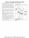
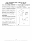
spacer ----.._ _
washer---_.._
hex nub---_
1/4" red tubing
from ROdrain
(connect to 1/4"
barb on faucet)
3/8" blue tubing
(connect to faucet.
tubing)
1/4" x 3/8"
quick connect
3/8" black tubing to
drain point (connect to
3/8" barb on faucet)
/
Figure 6
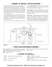
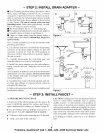
STEP 4: INSTALL RO ASSEMBLY -
Hang the assembly on the included hanger washers, or
lay on the cabinet flool; as desired.
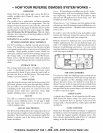
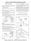
1. Refer to Figure 7 for wall mounting. Hold the assem-
bly up to the wall surface and mark locations for the
hanger washers. Distance needed is 7.2" (approx.
7-7/32") apart.
2. Install hanger washers at least 15-1/2" up from the
cabinet flool; allowing room to remove sumps from fit-
ter heads. Wood screws are provided, or obtain other
fasteners as needed.
3. Connect telephone style wire to the receptacle on the
electronics board, located on the top of the RO unit.
Route the wire through the strain relief notch on the
side of the manifold.
hanger
washer (2)
screw
15-1/2" min.
up from floor
Figure 7
7
Problems, Questions? Call 1-800-426-9345 Kenmore Water Line