


Setting Surface Controls
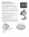
Setting the Dual Burner (SOME MODELS ONLY)
The Dual Burner has two rings of flame that you can control for two different
heat levels, one for small and one for large cookware.
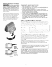
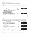
Large Cookware Operation (Figure 1; Zone A & B)
1. Place a large cooking utensil centered over the surface Burner Grate.
2. Push the surface control knob in and turn counterclockwise out of the OFF
position (See Figures 2 & 3).
3. Release the knob and rotate to the UTE position. Note: All electronic
surface ignitors will spark at the same time. However, only the dual Burner
will ignite.
4. Visually check that zone A & B of dual burner are lit (Figure 4). Adjust the
flame size by turning the control knob between the HI and the 2rid dot
settings (Figure 3). DO NOT cook with the surface control knob in the LITE
position (The electronic ignitor will continue to spark if the knob is left in the
LITE position).
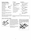
SrnaH Cookware Operation (Figure 1; Zone A)
1. Place a small cooking utensil centered over the dual surface Burner Grate.
2. Push the surface control knob in and turn counterclockwise out of the OFF
position.
3. Release the knob and rotate to the UTE position (Figures 2 & 3).
Note: All electronic surface ignitors will spark at the same time. However,
only the selected surface Burner will lite.
4. Visually check that zone A & B of the dual burner has lit.
5. Continue to rotate the gas control knob counterclockwise past the 2rid dot
setting; zone B flames will extinguish.
6. Visually check that only zone A is lit.
7. Continue to turn the control knob countercmockwise to adjust to the desired
flame size for the zone A. Note: The markings between the 2rid dot and Lo
settings on the control knob adjust the flame size for the zone A (Refer to
Figure 2 or 3). DO NOT cook with any of the surface control knobs in the
LITE position (The electronic ignitor will continue to spark if the knob is left
in the LITE position).
Figure 1
Figure 2
position
Dual Portion of
the Dual Burner
adjustment area
Single Portion of
the Dual Burner
adjustment area
Figure 3
Figure 4
12