


4. ADJUSTMENT
- 18 -
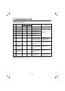
4-2 Introduction of E-Linear Compressor
E-Linear compressor is run by mechanical part design
through automatically varying the cooling power. The
main parts consist of compressor and Sub PCB which
controls the compressor. PCB authorizes constant
voltage and constant frequency to the compressor and
protects it.
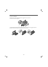
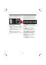
Drive half stroke after turning on initial power for 30
seconds. Then, slowly increase stroke and reach target
input. Once reaching the target input, input naturally
changes according to refrigerator load without any special
control.
Interval 1) Half stroke interval - after initial running, stay at
the initial value for 30 seconds
Interval 2) Running interval - Increase at every 0.8 till it
reaches the target input; it takes about
3 Minutes and 45 seconds.
Interval 3) CVCF interval - Run by target voltage and main
operating frequency and the input naturally
changes according to refrigerator load
❸
❶
❷
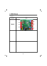
4-1-1 Role
4-1 COMPRESSOR
The compressor intakes low temperature and low pressure
gas from the evaporator of the refrigerator and compresses
this gas to high-temperature and high-pressure gas. It then
delivers the gas to the condenser.
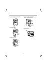
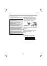
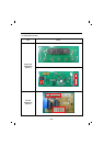
4-1-2 Note for Usage
(1) Be careful not to allow over-voltage and over-current.
(2) Do not drop or handle carelessly.
(3) Keep away from any liquid.
If liquid such as oil or water enters the Cover PTC
Compressor may fail due to breakdown of their
insulating capabilities.
(4) Always use the Parts designed for the compressor and
make sure it is properly attached to the compressor.
Parts may appear physically identical but could have
different electrical ratings. Replace parts by part number
and model number. Use only approved substitute parts.
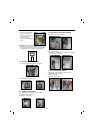
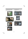
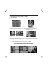
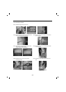
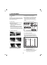
4-1-3 REMOVE THE COVER PTC
(1) Remove the Cover Back M/C
(2) Loosen two screws on comp base
(3) Use a L-shaped flap tooll to pry off the cover
(4) Assembly in reverse order of disassembly
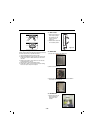
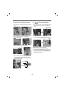
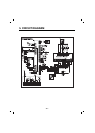
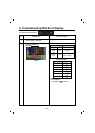
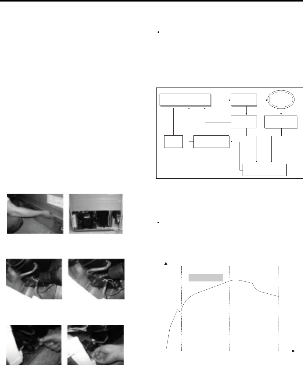
4-2-1 Control of Compressor Block Diagram
4-2-2 Compressor operating pattern
Compressor Controller Inverter
PWM
Signal
Frequ
-ency
Linear
Comp
DC link
Voltage
Main
Micom
Calculate counter
electromotive force
Counter elec-
tromotive force
Vcap Voltage
Control Block Diagram of Compressor
Comp. input