


- 59 -
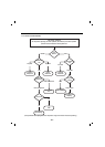
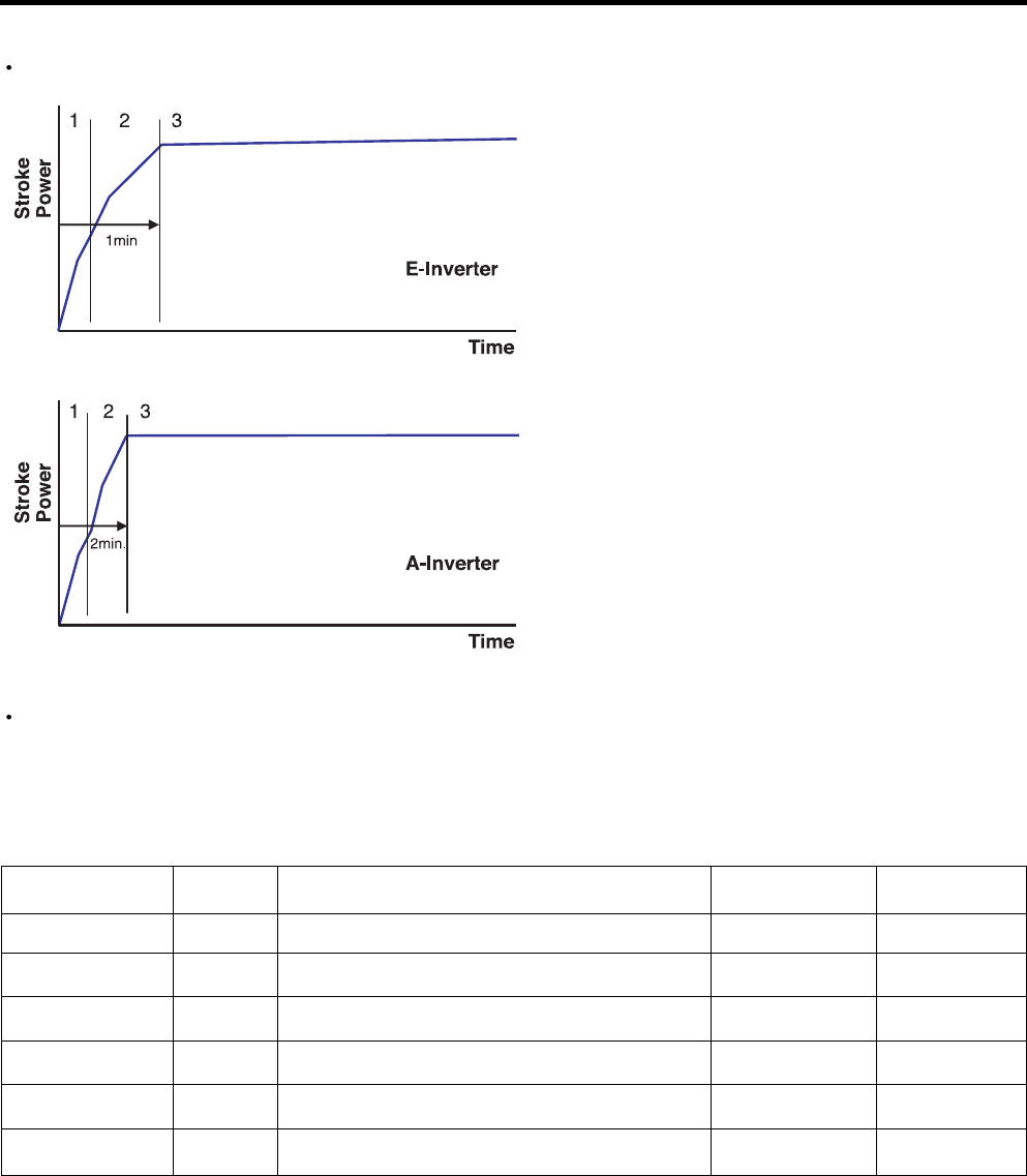
To reduce noise level, the piston stroke is slowly increased to full power during start up.
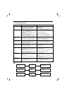
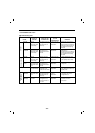
There are 6 protection logics designed to protect the linear compressor system. When a failure is detected,
the compressor will shut and will try to restart after a set period of time for each type of failure. The LED
located on the inverter drive PCB will flash the appropriate code to indicate the detected failure. This code will
continue to flash until the unit is disconnected from the power source.
Inverter Error Codes
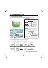
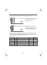
Step 1) Start up - Half stroke interval for first 1 second.
Step 2) Ramp up - Stroke increases every 0.8sec until
maximum stroke length is reached
(about 1 min)
Step 3) CVCF interval - 180V / 60Hz
Step 1) Start up - Half stroke interval for first 20
seconds.
Step 2) Ramp up - Stroke increases until maximum
stroke length is reached (about 1 min, 40 sec)
Step 3) VVVF interval - target voltage and frequency
controlled by Control Board signals
FCT0
Stroke Trip
Locked Piston
Trip
Current Trip
IPM Fault
Communication
Error
App.
A-Inv.
E-Inv.
A-Inv.
E-Inv.
A-Inv.
E-Inv.
A-Inv.
E-Inv.
A-Inv.
A-Inv.
Requirement
Compressor current and voltage error.
Piston stroke overrun detected.
Piston is locked.
Current overload detected.
High current detected due to IPM failure.
Miscommunication with Refrigerator
1
2
5
6
7
8
The number of
LED flashes
Waiting Time
20 sec.
1 min.
2 min. 30 sec.
6 min.
20 sec.
0