- 20 -
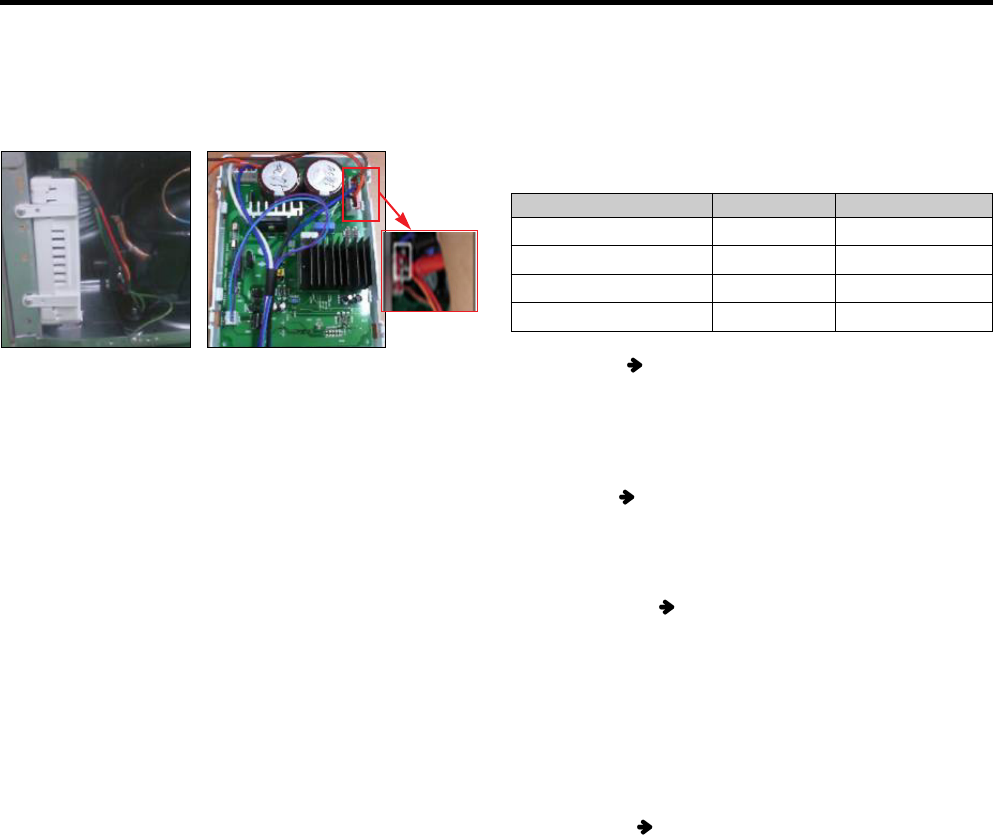
Measure the resistance between pin of the connector (as
shown picture) with a multi-tester.
Standard for normality
- In order to decide whether compressor operating is normal
or not, check the output transfer during the refrigerator
operation.
- After input the initial power and compressor operates, wait
for 10 minutes to estimate.
- Compressor operation may be diagnosed as normal if the
voltage falls between 145V and 180V.
Warning
1. Please be cautious of electric shock and short (it is
estimated after turning on initial power).
2. If the voltage is estimated less than 80V, it is diagnosed
as bad.
2) Check to normality by measurement of Voltage
If compressor protection logic is running, LED Lamp’s
blinking frequency of sub PCB, which takes in charge of
control, can help estimate the protection logic’s symptoms
and the cause of its problems.
Trip name
Stroke Trip
Current Trip
Lock Piston Trip
IPM fault trip
Led Times
2
6
5
7
Comp Off Time
1min
6min
2min 30sec
20sec
3) Check problems by LED On & Off Count _ (Sub PCB)
- Current Trip PCB defects or Cycle clogging maybe the
causes. After estimating winding resistance, estimate
compressor operation voltage to check if there is any
problem and take actions to repair cycle at replacement of
compressor.
- Stroke Trip
can occur when the surrounding
temperature is high, C-Fan, F-Fan and so on are
constrained, or when cycle problems, such as moisture
blocking or compressor defect, are related.
- Lock Piston Trip
Since compressor itself can be a
potential cause of a defect, estimate the compressor
resistance value according to #1’s compressor winding
value estimation method and estimate the #2’s
compressor operation voltage to decide whether it is
defective or not
(Before replacement of compressor, replace PCB and
conduct the replacement of compressor during
compressor replacement)
- IPM fault Trip
Replace sub PCB since there is high
chance that it is caused by sub PCB’s part defect.
<Fig. 1> <Fig. 1>


