


43
Section Three
POWER CLEAN FILTER MODELS
WITH INTERNAL WATER FEED
Models: GU940SCG, GU960SCG, GU980SCG
THEORY OF OPERATION
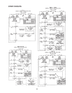
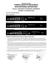
Console Configurations
Model GU940SCG
Model GU960SCG
Model GU980SCG
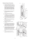
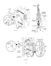
1. Once the tub has filled with hot water the motor begins to rotate forcing the water up through the pump
chamber and out through the spray arms. Two spray jets on the underside of the lower spray arm direct water
down onto the fine mesh screen of the pump housing to clear soils that may collect there during the wash
cycle.
(Fig. 3-1)
2. As water and soils return to the lower pump area, the chopper blade grinds the particles into smaller sizes
that then pass through the perforated plate into the upper chamber of the pump. The pump impeller causes
the soil ladened water to be lifted and moved to the outer edges of the pump chamber where they are forced
into the separator. Clean water is then forced up through the spray arms and fine mesh screen.
(Fig. 3-1)
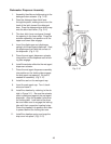
3. When the drain cycle begins, the drive motor changes direction. This relieves the pressure on the two check
balls, opening the drain system.
4. Water is pumped from the tub carrying soils from the separator into the drain sump of the pump.
(Fig. 3-2)
5. Soiled water is pumped out of the dishwasher through the check valve and drain hose.
(Fig. 3-3)
Fig. 3-2
POWER CLEAN FILTER Pump and Motor Operation
Fig. 3-3Fig. 3-1