


4
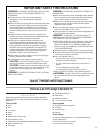
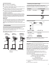
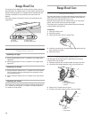
24" (61 cm) min.
30" (76.2 cm)
suggested max.
bottom of hood to
cooking surface
18" (45.7 cm)
min. clearance
upper cabinet
to countertop
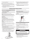
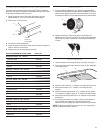
Venting Requirements
■ Use a straight run or as few elbows as possible.
■ Do not terminate the vent system in an attic or other enclosed
area.
■ Do not use a 4" (10.2 cm) laundry-type wall caps.
■ Vent system must terminate to the outside.
■ Use only a 6" (15.2 cm) round metal vent. Rigid metal vent is
recommended. Do not use plastic or metal foil vent.
■ The size of the vent should be uniform.
■ The vent system must have a damper. If roof or wall cap has a
damper, do not use damper supplied with the range hood.
■ Use duct tape to seal all joints in the vent system.
■ Use caulking to seal exterior wall or roof opening around the
cap.
■ Determine which venting method is best for your application.
Installation clearances
Location Requirements
IMPORTANT: Observe all governing codes and ordinances.
■ It is the installer’s responsibility to comply with installation
clearances specified on the model/serial rating plate. The
model/serial rating plate is located inside the range hood on
the rear wall.
■ Range hood location should be away from strong draft areas,
such as windows, doors and strong heating vents.
■ Cabinet opening dimensions that are shown must be used.
Given dimensions provide minimum clearance. Consult your
cooktop/range manufacturer installation instructions before
making any cutouts.
■ Grounded electrical outlet is required. See “Electrical
Requirements” section.
■ The hood is factory set for vented installations. For
recirculating installations, Recirculation Kit Part Number
4396565, including vent cover and 2 charcoal filters are
available from your dealer.
■ All openings in ceiling and wall where range hood will be
installed must be sealed.
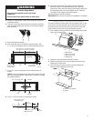
70⁵⁄₁₆"
(178.6 cm)
min.
76⁵⁄₁₆"
(193.8 cm)
max.
to bottom of
cabinet frame
36" (91.4 cm)
countertop
height
30" (76.2 cm) or
36" (91.4 cm) min.
cabinet opening width
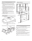
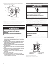
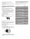
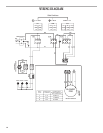
Product dimensions
9
¹⁵⁄₁₆
"
(25.2 cm)
9
¹⁄₈
"
(23.2 cm)
3¹⁵⁄₁₆"
(10.0 cm)
29¹⁵⁄₁₆" (76.0 cm) – 30" (76.2 cm) model
35
¹⁵⁄₁₆" (91.3 cm) – 36" (91.4 cm) model
20
³⁄₁₆
"
(51.3 cm)
1³⁄₁₆"
(3.0 cm)
1¹⁄₄"
(3.2 cm)
centerline
of hood
electrical
knockouts
centerline of
exhaust collar
1
⁵⁄₁₆"
(3.3 cm)
1
⁵⁄₁₆"
(3.3 cm)
5
⁷⁄₈
"
(14.9 cm)
dia.
7
¹⁄₂
"
(19.0 cm)
5
⁷⁄₈
" (14.9 cm) dia.
exhaust collar
Interchangeable
Front Trim
Vent and electrical openings and mounting screw locations