


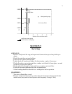

To provide correct pressure of the fuel supply to your stove, the tank outlet should be
between 16” and 72” above the carburetor on the stove. Do not exceed 72” above the
carburetor as excessive head pressure could limit the carburetor’s ability to shut off fuel flow.
Be sure the support system under the tank is safe and adequate as a full 300 gallon tank will
weigh about 2000 lb.
If you must install a tank below the stove, or above the recommended height, a lift pump
and/or a level control valve must be fitted. You will need to check local building codes
regarding such installations.
CONNECTIONS:
There should be 2 valves on a typical installation: 1) a shut-off valve at the tank to allow
service to any piping, or changing the main filter and 2) a shut-off valve close to the stove to be
able to isolate the stove for any maintenance, and (if required by code) a fire valve right before
the fuel pipe enters the building which would automatically shut off the oil supply in the
unlikely event of the stove overheating. Piping to the stove from the tank may be either steel or
copper, but copper is preferred to prevent any rusting problems. When making the fuel line
connection with the copper line from the tank to the stove, it is best to have a gradual slope or
“fall” on the line (i.e. no dips or kinks) so as to prevent any air bubbles or collection of dirt or
other impurities. A 3/8” diameter copper supply line is recommended and either compression
type or flare type fitting may be used. Finally, a good quality filter that also traps water should
be placed at the tank to ensure a good, clean supply of oil to your stove. The carburetor on the
stove is equipped with a screen-type filter but it is not intended for use as the primary filter.
SECTION 4
Lighting, carburetor adjustments, and draft stabilizer adjustments
PRE-LIGHTING CHECKS:
The installation should be inspected to ensure that the work is complete and the
workmanship is satisfactory. No stove should be lit if any part of the installation does not
comply with the relevant standards and regulations.
The oil tank should be examined to confirm there is a supply of the correct grade of oil,
that a filter and a working isolation valve are fitted. Having verified that the oil pipe work up to
the stove is complete and that the fire valve (if used) is closed, the tank isolation valve should
be opened and the pipe work inspected for leaks. The pipe into the inlet of the metering valve
should be uncoupled, the shut off valve opened and a minimum of one quart of oil collected
into a suitable receptacle. If dirt or water is present in this sample, additional oil should be
allowed through the pipe work until it is free from contaminates. The fuel pipe work should be
reassembled and all connections checked for leaks and tightened as necessary.
For 7” Burner Models: Laying on top of the catalyst inside your Oil Classic 7” burner
model stove is a stainless steel top burn ring. It is important that the ring be in the proper
position. It comes in the proper position from the factory. Should the height of this ring
change, it is easy to re-adjust by bending the three tabs that rest on the catalyst top up or
down. It is very important that the “cupped” part of the ring is facing up (as if it would hold
water). The stove will not burn properly if the ring is face down. Locate the two continuous
rows of air holes circling the burner top. The top ring tabs should set on the catalyst top so
that the outer edge of the ring comes out right between those two rows of air holes.
LIGHTING:
Initial lighting should be undertaken by a qualified technician, with a suitable probe-
type manometer for checking the flue pressure. Although adjusting the draft stabilizer by “feel”
4