


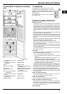
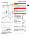
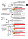
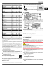
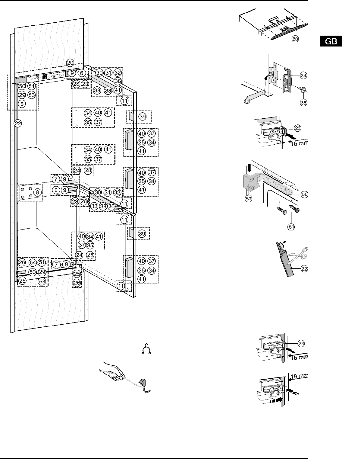
4.3.1 Installing the appliance
Fig. 8
u
Detach the connecting cable from the rear of the appli-
ance. Remove the cable holder otherwise there will be
vibratory noise.
u
Lay the connecting cable with
the help of string in such a way
that the appliance can be easily
connected following installation.
Fig. 9
For appliances with permanently plumbed in IceMaker:
u
Connect the IceMaker (see 4.2) .
All appliances:
u
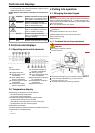
Slide the appliance 3/4 of the way into the recess.
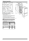
u
Remove the covers
Fig. 8 (5,6,7)
.
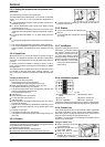
u
Fit the equaliser trim
Fig. 10 (20)
concentrically
onto the appliance: Slide it
into the recess and engage
it in the keyholes.
Fig. 10
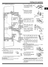
u
Screw all the mounting
brackets
Fig. 11 (34)
to the
pre-drilled holes in the ap-
pliance door using hexa-
gon screws
Fig. 11 (35)
.
Fig. 11
For 16 mm-thick unit walls =
568 mm-wide recess:
u
Clip spacer
Fig. 12 (23)
onto the
upper hinge and spacer
Fig. 8 (24)
onto the lower hinge.
Fig. 12
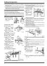
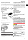
u
Attach the top cover
Fig. 13 (53)
and bottom cov-
er
Fig. 13 (50)
to the mount-
ing brackets.
u
Fasten the mounting brack-
ets
Fig. 13 (50)
at the top and
bottom with screws
Fig. 13 (51)
so that the brack-
ets can still be moved a little
to the left and right.
Fig. 13
u
Strip the protective film off the cover trim
Fig. 14 (22)
. Apply the cover trim
Fig. 14 (22)
to the projection of the cover
Fig. 13 (53)
on the handle side, flush with the
front, and adhesively affix it to the side wall
of the appliance.
u
If necessary, shorten the cover strip
Fig. 14 (22)
at the bottom: The cover strip
Fig. 14 (22)
has to end 3 mm above the up-
per edge of the lower mounting bracket
Fig. 8 (50)
.
Fig. 14
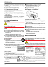
Slide in and align the appliance:
u
Slide in the appliance until the covers
Fig. 13 (53)
abut
Fig. 13
against the side wall of the kitchen unit.
u
Extend the adjustable foot.
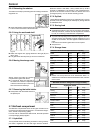
For 16 mm-thick unit walls =
568 mm-wide recess:
u
Allow the spacers to abut
against the side wall of the kitch-
en unit.
Fig. 15
For 19 mm-thick unit walls =
562 mm-wide recess:
u
Align the front edges of the hing-
es so as to be flush with the side
wall of the kitchen unit.
Fig. 16
For kitchen units (16 mm and 19 mm) with door stop
components (knobs, sealing lips etc.):
u
Allow for the extra distance (depth of the door stop compo-
nents): Allow hinges and covers
Fig. 13 (53)
to protrude by the
extra distance.
All appliances:
Putting into operation
7