


u
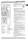
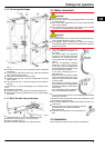
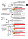
Vertically align the appliance by means of the adjustable-
height feet
Fig. 8 (25)
, using the accompanying open-ended
spanner
Fig. 8 (26)
.
w
The appliance is now correctly positioned in depth. The dis-
tance from the front edge of the side wall of the unit to the
appliance body is 42 mmall the way round. (Allow for door stop
components, such as knobs and sealing lips.)
Note
Incorrect installation will lead to malfunction!
If the distance is not kept, the door may not close. This may lead
to icing, to condensate forming and to malfunction.
u
Be sure to keep to the clearance of 42 mm all the way round.
(Allow for door stop components, such as knobs and sealing
lips.)
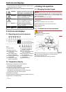
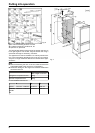
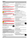
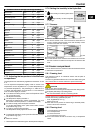
Tightly screw the appliance into place in the recess:
u
At the top and bottom of
both doors with Spax
screws
Fig. 17 (28)
passed through the
hinge plates.
Fig. 17
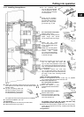
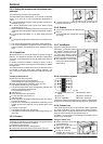
On the handle side at the top:
u
Loosen the screws
Fig. 18 (55)
a little.
u
Tightly screw the top
mounting bracket
Fig. 18 (50)
to the unit wall
using Spax screw
Fig. 18 (29)
ø4x19.
u
Break off the projecting
end of the cover
Fig. 18 (53)
.
Fig. 18
u
Tighten the screws
Fig. 18 (55)
.
u
Put on the cover
Fig. 18 (53)
.
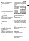
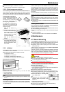
On the handle side at the bottom:
u
Loosen the screws
Fig. 19 (51)
a little.
u
Tightly screw the bottom
mounting bracket
Fig. 19 (50)
to the unit wall
using Spax screw
Fig. 19 (29)
ø4x19.
u
Break off the projecting end
of the cover
Fig. 19 (53)
. It
is no longer required.
u
Tighten the screws
Fig. 19 (51)
.
u
Put the cover
Fig. 19 (54)
on
the bottom mounting brack-
et
Fig. 19 (50)
.
Fig. 19
u
Close the appliance door.
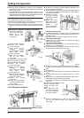
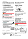
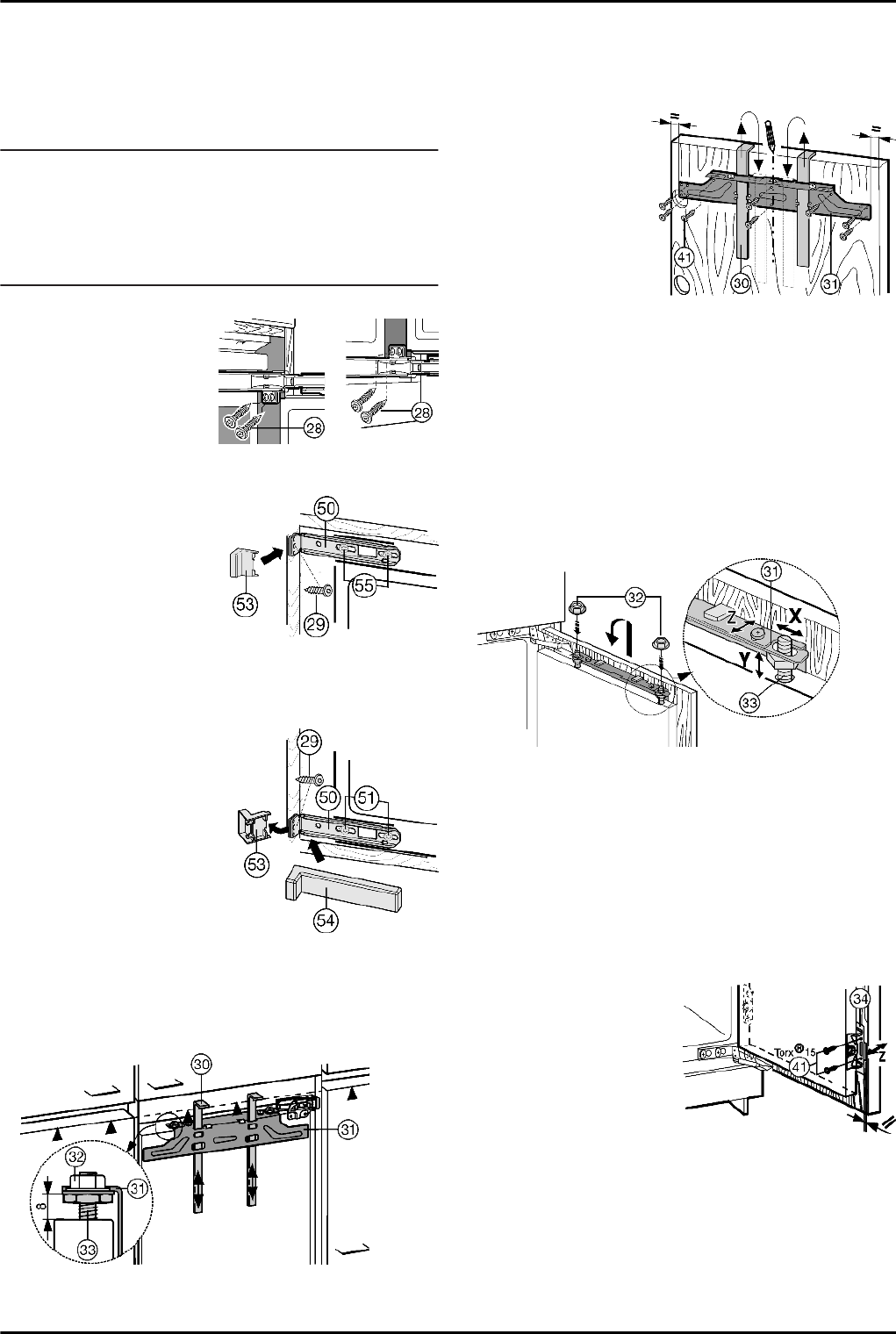
4.3.2 Fitting the unit doors
Fig. 20
The fitting aids
Fig. 20 (30)
are required for both doors. There-
fore fit the unit doors one after the other.
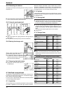
u
Check 8 mm-presetting. (Distance between appliance door
and lower edge of crosspiece)
u
Slide up the assembly aids
Fig. 20 (30)
to the height of the unit
door. Lower stop edge ▲of the assembly aid = upper edge of
the unit door to be fitted.
u
Unscrew the cross-
piece
Fig. 21 (31)
by
undoing the locknuts
Fig. 21 (32)
.
u
Attach the cross-
piece
Fig. 21 (31)
to-
gether with the as-
sembly aids
Fig. 21 (30)
to the in-
side of the unit door.
Fig. 21
For 600 mm-wide recess:
u
Concentrically align the crosspiece
Fig. 21 (31)
: Mark a short
centre line on the unit door and put the tip of the arrow on the
crosspiece over it.
w
Distances to the outer edge are equal at the left and right.
For particle board doors:
u
Tightly screw the crosspiece
Fig. 21 (31)
into place using at
least 6 screws
Fig. 21 (41)
.
For frame and panel doors:
u
Tightly screw the crosspiece
Fig. 21 (31)
into place using 4
screws
Fig. 21 (41)
at the edge.
u
Raise and remove the assembly aids
Fig. 21 (30)
, turn them
and slide them into the adjacent openings.
Fig. 22
u
Attach the unit door to the adjusting bolts
Fig. 22 (33)
and
loosely screw the locknuts
Fig. 22 (32)
onto the adjusting
bolts.
u
Close the door.
u
Check the gap between the door and the surrounding unit
doors.
u
To laterally align the unit door: Move the unit door in the X
direction.
u
Align unit door in height and lateral inclination: Adjust the ad-
justing bolts
Fig. 22 (33)
using a screwdriver.
w
The unit door is flush and in alignment with the surrounding
unit fronts.
u
Tighten the lock nuts
Fig. 22 (32)
.
Ensure that both metal
edges are flush (sym-
bol //):
u
Drill pilot holes in the
door of the unit (possi-
bly make preliminary
hole with a bradawl).
Fig. 23
u
Screw the appliance door to the unit door with screws
Fig. 23 (41)
passed through the mounting brackets
Fig. 23 (34)
.
Putting into operation
8