


3 Controls and displays
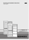
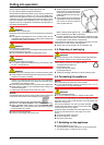
3.1 Operating and control elements
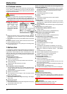
Fig. 3
(1) Alarm button (8) Fan button
(2) SuperCool button (9) Temperature display
(3) On/Off button (10)Fan symbol
(4) Alarm symbol (11)Child-proofing symbol
(5) Menu symbol (12)SuperCool symbol
(6) Down setting button (13)Net@Home symbol
(7) Up setting button
3.2 Temperature display
The following are displayed in normal operation:
-
the average cooling temperature
The following displays indicate malfunction. Possible causes and
corrective action (see Malfunction).
-
F0 to F9
4 Putting into operation
4.1 Changing over the door hinges
You can change over the door hinges if necessary.
NOTICE
Risk of damage to side-by-side appliances due to condensation!
When a Side-by-Side appliance (S…) is fitted together with a
second appliance (as a SBS combination), the door hinges must
remain as delivered.
u
Do not change over the door hinges.
Ensure that the following tools are to hand:
q
Torx 25
q
Torx 15
q
Screwdriver
q
Cordless screwdriver, if necessary
q
Second person for fitting work, if needed
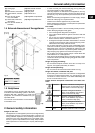
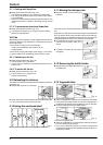
4.1.1 Detaching the door
Note
u
Remove any food from the door racks before removing the
door, so that no food falls out.
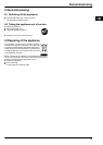
Fig. 4
u
Close the door.
u
Pull off the cover
Fig. 4 (10)
forwards and upwards.
u
Lift off the cover
Fig. 4 (11)
.
CAUTION
Risk of injury if the door tips!
u
Take good hold of the door.
u
Set down the door carefully.
u
Unscrew the upper turn hinge
Fig. 4 (12)
(2 Torx 25)
Fig. 4 (13)
and raise it for removal.
u
Lift up the door and set it aside.
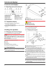
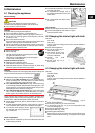
4.1.2 Changing bearing parts
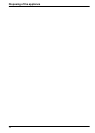
Fig. 5
u
Draw the safety lock
Fig. 5 (21)
forwards for removal.
u
Remove the cover
Fig. 5 (27)
.*
u
Fully retract the adjustable-height foot
Fig. 5 (22)
.
u
If necessary, tip the appliance back a little with the assistance
of a second person for removal of the bearing pin.
u
Pull out the bearing pin
Fig. 5 (22)
downwards and forwards.
In so doing, pay attention to the hinge bush
Fig. 5 (20)
.
u
Unscrew the turn hinge
Fig. 5 (23)
(2 Torx 25)
Fig. 5 (24)
.
u
Unscrew the bearing part
Fig. 5 (26)
(1 Torx 25),
Fig. 5 (28)
,
transfer it to the opposite hole in the turn hinge and screw it
down again.
u
Carefully lift off and transfer the cover
Fig. 5 (25)
on the handle
side.
u
Screw down the turn hinge
Fig. 5 (23)
on the new hinge side,
possibly with the aid of a cordless screwdriver, through the
outer oblong hole and round hole.
Note
u
If necessary, e.g. to make up for any unevenness in the floor,
the second oblong hole can be used instead of the round hole
for the screw fitting.
Controls and displays
4