


u
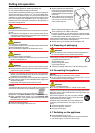
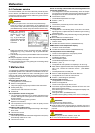
Tip the appliance back a little
again and re-insert the bear-
ing pin
Fig. 6 (22)
. The notch
has to point forwards.
u
Place the cover
Fig. 5 (27)
on
the opposite side.*
Fig. 6
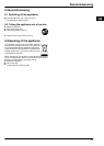
CAUTION
Risk of injury if the door tips!
u
The safety lock
(21)
has to engage with the turn hinge at the
side so that the bearing pin and therefore the door are se-
cured.
u
u
Snap the safety lock
(21)
onto the turn hinge again.
u
Put on the hinge bush
Fig. 5 (20)
.
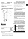
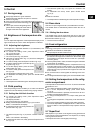
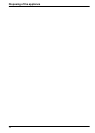
4.1.3 Transferring the handle
u
Disengage the spring clip
Fig. 7 (34)
from the door and transfer
it to the new hinge side.
u
Lift the stopper
Fig. 7 (30)
out of the door bearing bush and
transfer it.
Fig. 7
u
Detach door handle
Fig. 7 (31)
, stoppers
Fig. 7 (32)
and pres-
sure plates
Fig. 7 (33)
plates and transfer to the opposite side
u
When fitting the pressure plates at the opposite side, pay at-
tention that they engage properly.
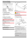
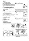
4.1.4 Fitting the lower door
u
Place the door from above onto the lower bearing pin
Fig. 5 (22)
.
u
Close the door.
u
Insert the upper turn hinge
Fig. 4 (12)
in the door on the new
hinge side.
u
Screw down the upper turn hinge
Fig. 4 (12)
(2 Torx 25)
Fig. 4 (13)
. Possibly make preliminary holes with a bradawl or
use a cordless screwdriver.
u
Snap the cover
Fig. 4 (10)
and cover
Fig. 4 (11)
into place at
the opposite side.
4.1.5 Aligning the door
u
Transfer the middle screw on the lower turn hinge
Fig. 5 (23)
into the free oblong hole.
u
Align the door to the appliance housing by way of the two ob-
long holes in the lower turn hinge
Fig. 5 (23)
.
u
Tighten the screws.
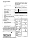
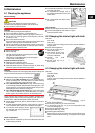
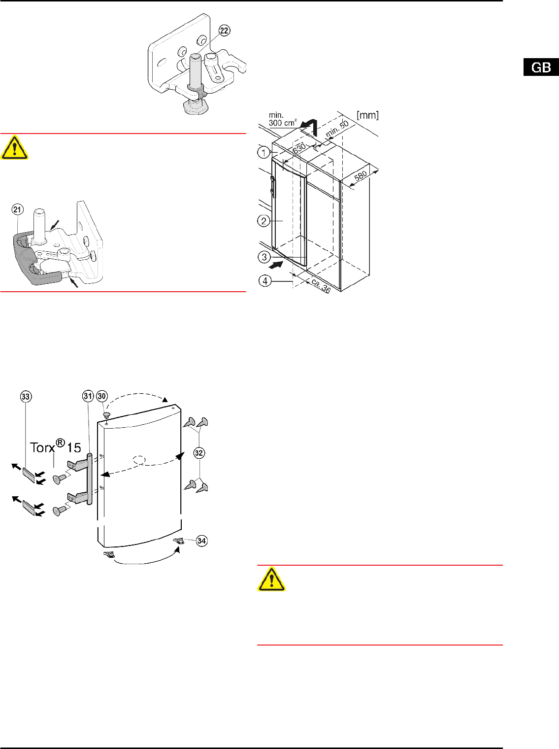
4.2 Insertion into a row of kitchen units
Fig. 8
(1) Stack cabinet (3) Kitchen cabinet
(2) Appliance (4) Wall
The appliance can be inserted into a row of kitchen units. To
match the appliance
Fig. 8 (2)
to the height of the row of units, a
suitable stack cabinet
Fig. 8 (1)
can be fitted above the appliance.
When inserting the appliance into a row of standard kitchen units
(max. depth 580 mm), the appliance can be installed directly next
to the kitchen unit
Fig. 8 (3)
. The appliance door projects relative
to the front of the kitchen unit by 34 mm at the side and by
50 mm in the middle of the appliance. It can be opened and
closed perfectly as a result.
Important for the ventilation:
-
At the back of the stack cabinet there has to be a ventilation
duct of at least 50 mm depth throughout the width of the stack
cabinet.
-
The ventilation space under the ceiling has to be at least
300 cm
2
.
-
The larger the ventilation space, the more energy-saving the
appliance is in operation.
If the appliance is installed with the hinges next to a wall
Fig. 8 (4)
, the distance between appliance and wall has to be at
least 36 mm. This corresponds to the projection of the handle
when the door is open.
4.3 Transporting the appliance
CAUTION
Risk of injury and danger of damage as a result of incorrect trans-
port!
u
Transport the appliance in a packed condition.
u
Transport the appliance upright.
u
Do not transport the appliance without assistance.
4.4 Installing the appliance
In the event that the appliance is damaged, contact the supplier
immediately before connecting to the mains.
The floor at the site must be flat and level.
Do not install the appliance in a location where it is exposed to
direct radiation of the sun, next to a cooker, heater and similar.
Putting into operation
5