Impinger X2 – Digital Service Manual – Dom & Int’l
3
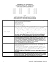
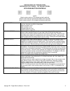
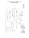
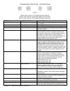
SEQUENCE OF OPERATION
IMPINGER X2 OVENS - INTERNATIONAL
WITH PUSH BUTTON CONTROLS
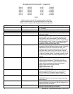
3240-2* 230VAC 50 HZ. 1 PHASE
3262-2* 230VAC 50 HZ. 1 PHASE
3270-2* 230VAC 50 HZ. 1 PHASE
*NOTE:
Model number ending in TS indicates top belt is split belt
Model number ending in SB indicates bottom belt is split belt
Model number ending in SS indicates both belts are split belts
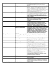
POWER SUPPLY Electrical power to be supplied to the oven by a three conductor service for single phase
or a four conductor service for three phase.
Black conductor is hot.
Red conductor is hot.
Orange conductor is hot.
Green conductor is ground.
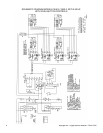
MAIN FAN CIRCUIT Power is permanently supplied to the normally open contacts of the main fan relay.
Power is also supplied, through a 3 amp. fuse, to the 30 minute time delay relay.
Closing the oven power switch enables the 30 minute time delay relay. The 30 minute
time delay relay supplies line voltage to the coil of the main fan relay. These normally
open contacts now close energizing the main fan motor. Closing the main power switch
also supplies power to the burner and conveyor circuits.
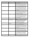
BURNER CIRCUIT Closing the oven power switch supplies line voltage, through the air pressure switch and
through the oven cavity hi-limit thermostat, to the burner control. The burner control
supplies line voltage to the burner blower motor. The normally open air pressure switch
closes upon sensing air pressure. The spark and pilot valve are now energized. Ignition
should now occur. After the pilot flame is proven, the main gas valve is energized.
TEMPERATURE CONTROL Closing the main fan switch supplies line voltage, through a filter, to the oven control
transformer. The transformer’s secondary supplies 24VAC to the oven control. The oven
control is set to the desired temperature. The thermocouple will provide varying millivolts
to the oven control. The oven control supplies line voltage to the temperature regulation
valve at intermittent intervals to maintain desired temperature. The display on the oven
control will indicate when the temperature regulation valve is energized.
NOTE: The display also indicates oven temperature.
CONVEYOR DRIVE
THE OVEN WILL CONTAIN BETWEEN TWO AND FOUR SEPARATE CONVEYOR
DRIVE SYSTEMS. THE SEQUENCE OF OPERATIONS WILL BE THE SAME FOR
EACH MOTOR SYSTEM.
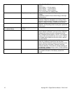
Closing the main fan switch supplies line voltage, through a filter, to the conveyor motor
and, through a filter, to the primary of the control transformer. Secondary voltage,
24VAC, is supplied to he oven control. Setting the oven control to the desired time,
outputs voltage, through a reversing switch, to the conveyor motor.
NOTE: The conveyor control uses a hall effect sensor and magnet to prove operation of
the conveyor motor. If the conveyor motor is not running, “STALL” is indicated on the
display.
AUTOMATIC COOL DOWN When the oven is started, the 30 minute time delay relay is enabled, permitting the oven
fan to operate for approximately 30 minutes after the oven is shut off, to cool the oven.
When the oven is shut off, the 30 minute time delay relay will keep the coil of the main
fan relay closed for 30 minutes, maintaining operation of the main fan motor.


