


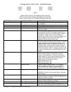

Impinger X2 – Digital Service Manual – Dom & Int’l
8
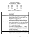
present, trace wiring back to burner control. If voltage is
present, check for gas pressure at the pilot line
connection. If no gas pressure is present during
ignition, check for any blockage in the assembly. If
there are no obstructions, and there is gas supplied to
the oven, replace the gas valve.
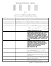
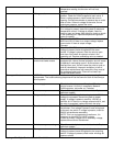
No pilot flame If the ignition control is supplied with 24VAC and the
pilot valve and igniter circuits are energized, visually
check for a pilot flame. This may be done by looking
through the inspection view port on the end of the
burner. If no pilot flame is visible, check the pilot tube.
Pilot tube Check for gas pressure at the pilot tube. Disconnect
pilot tube at the burner And connect manometer to pilot
tube. If no gas pressure is present during ignition,
check for blockage of the pilot tube. If the pilot tube is
clear, proceed.
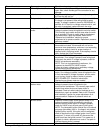
Pilot orifice If there is gas pressure at the pilot tube, check the pilot
orifice for blockage or obstructions. Replace pilot orifice
as needed.
Burner igniter Check the burner igniter head for any damage or
obstructions also check for frayed or broken wire.
Check spark gap, gap should be 3/32” If there is visible
damage, replace burner igniter.
NOTE: Flame should be
on at this time
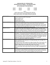
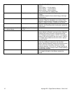
Low flame is on, but no main
flame
Transformer, burner/control Check for 208/240VAC supplied to primary of
transformer. If no voltage is present, trace wiring back
to the main fan switch. If voltage is present, check for
24VAC at transformer secondary.
NOTE: This is a dual secondary transformer, it is
important to check BOTH 24VAC outputs.
If there is primary voltage but no secondary voltage,
replace burner/control transformer.
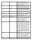
Oven control Check for 24VAC supply to oven control. If no voltage
is present, trace wiring back to control transformer. If
24VAC is present, check for a read-out on the display.
If there is 24VAC supplied, but there is no read-out on
the display, replace oven control. If there is a read-out
on the control, set the control to maximum temperature
(see Installation operations manual for temperature
adjustment). With the control set at maximum
temperature, check for 208/240VAC at the temperature
regulation valve. If there is voltage at the temperature
regulation valve, proceed to “Temperature regulation
valve” for next check. If there is no voltage at the
temperature regulation valve, trace wiring back to the
oven control. If there is no voltage output at the oven
control, check the read-out on the oven control. If the
control reads “PROBE FAIL”, this indicates that the
thermocouple has failed or become disconnected from
the oven control.
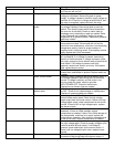
Thermocouple probe Check to be sure that the thermocouple is securely
connected to the oven control. If the thermocouple is
connected to the oven control, and the control indicates
“PROBE FAIL”, disconnect the thermocouple from the
oven control and measure the resistance of the
thermocouple. The thermocouple should read approx.
11Ω. If these readings are not achieved, replace the
thermocouple. If these readings are correct, proceed.
Oven control If the thermocouple checks good, but the oven control
display indicates that there is a thermocouple failure,