


Installation Instructions Section 2
2-6
Part No. 80-1214-3
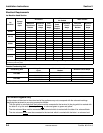
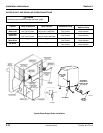
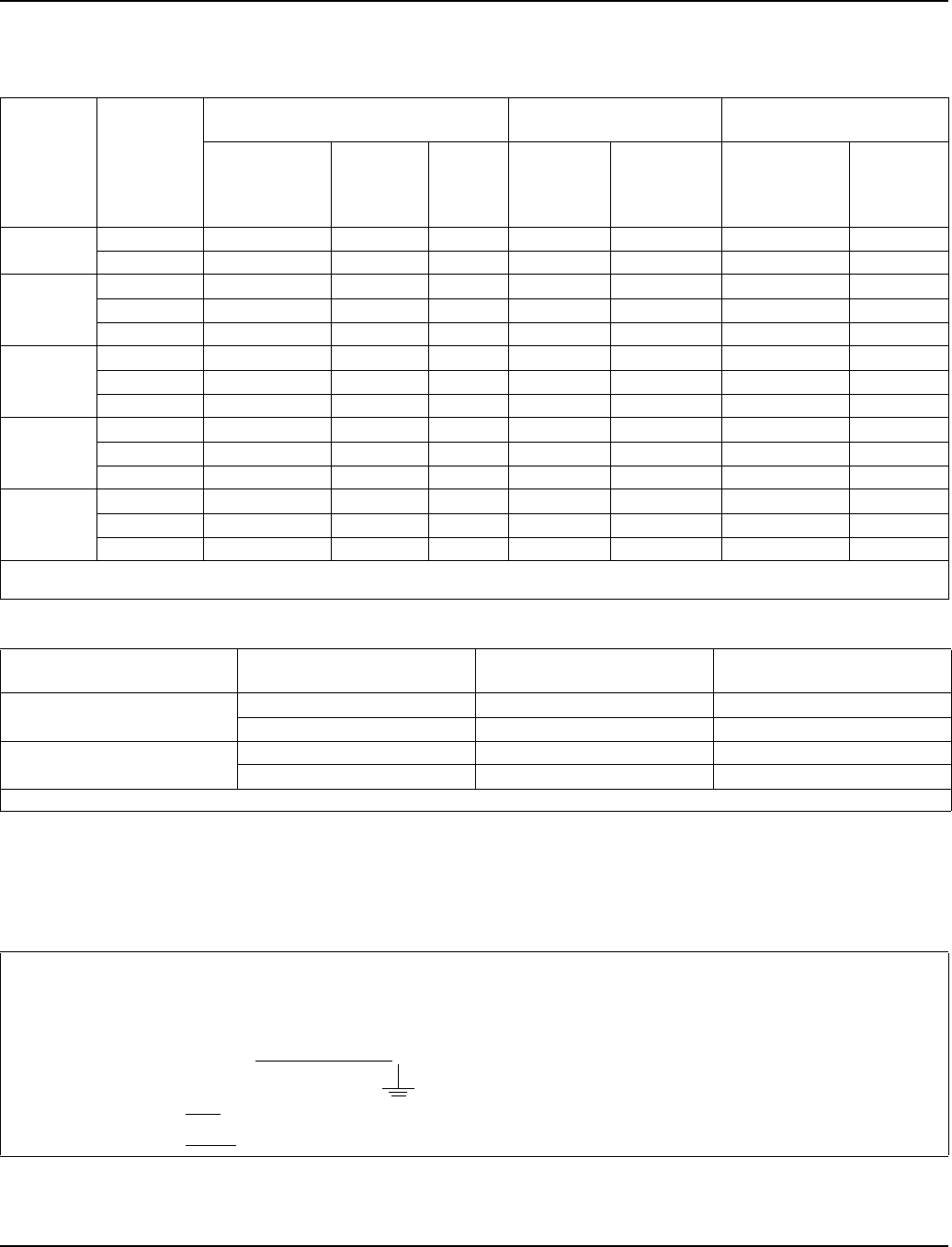
Electrical Requirements
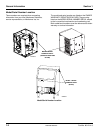
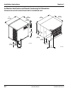
Ice Machine Head Section
Remote Condensing Unit
Ice
Machine
Voltage
Phase
Cycle
Air-Cooled
Remote
Air-Cooled
Water Cooled
Maximum
Fuse/Circuit
Breaker
Minimum
Circuit
Amps
Total
Circuit
Amps
Maximum
Fuse/
Circuit
Breaker
Minimum
Circuit
Amps
Maximum
Fuse/Circuit
Breaker
Minimum
Circuit
Amps
QF400
115/1/60 15 NA 9.8 NA NA NA NA
230/1/50 15 NA 4.2 NA NA NA NA
QC700
115/1/60 30 18.9 NA NA NA 30 17.9
230/1/50 20 8.8 NA NA NA 20 8.4
230/1/60 15 8.7 NA NA NA 15 8.3
QF800
115/1/60 30 18.9 NA NA NA 30 17.9
230/1/50 20 8.8 NA NA NA 20 8.4
230/1/60 15 8.7 NA NA NA 15 8.3
QF2200
115/1/60 NA NA NA 15 4.3 NA NA
230/1/50 NA NA NA NA NA NA NA
230/1/60 NA NA NA NA NA NA NA
QF2300
115/1/60 NA NA NA 15 5.5* NA NA
230/1/50 NA NA NA NA NA NA NA
230/1/60 NA NA NA NA NA NA NA
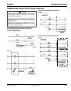
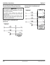
Interconnecting wiring (115/60/1) is required between the ice machine and condensing unit to energize the contactor coil.
* Indicates preliminary data
Condensing Unit
Voltage Phase
Cycle
Maximum Fuse/Circuit
Breaker
Minimum Circuit Amps
RFC2085
208-230/1/60
30 15.6
208-230/3/60
20 11.2
RFC2385
208-230/1/60
30 18.5*
208-230/3/60
20 11.2*
* Indicates preliminary data
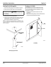
For United Kingdom Only
As the colours of the wires in the mains lead of the appliance may not correspond with the coloured markings
identifying the terminals in your plug, proceed as follows:
• The wire which is coloured green and yellow
must be connected to the terminal in the plug which is marked with
the letter E or by the earth ground symbol or coloured green or green and yellow.
• The wire coloured blue
must be connected to the terminal which is marked with the letter N or coloured black.
• The wire coloured brown
must be connected to the terminal which is marked with the letter L or coloured red.
Revised 8/2003