


Electrical System Section 6
6-4
Part No. 80-1214-3
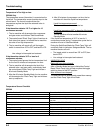
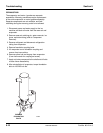
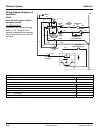
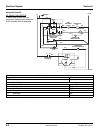
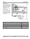
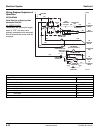
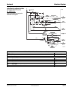
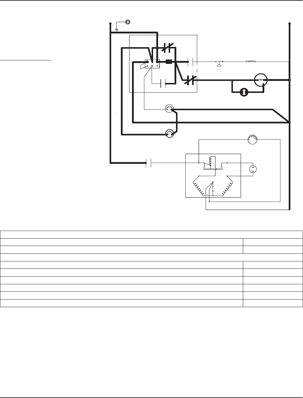
Wiring Diagram Sequence of
Operation
QF400
Initial Start-Up or Start-Up After
Automatic Shut-Off
1A. WATER FLUSH
Immediately after placing the toggle
switch in “ICE”, the dump valve
solenoid, and gearbox are energized.
After 45 seconds the dump valve de-
energizes.
RELAY
K1
SV3033
GROUND
L1
L2 (N)
(21)
(65)
CONTACTOR
COIL
(90)
HIGH
PRESSURE
CUT-OUT
(95)
RELAY
K2
RELAY
K3
RELAY K4
(25)
10 AMP
FUSE
(46)
GEARMOTOR
(47)
GEARMOTOR
RUN CAPACITOR
(48)
(43)
(56)
WATER FLOAT
VALVE COIL
(52)
(22)
(55)
(51)
DUMP VALVE
COIL
FAN MOTOR
(AIR-COOLED ONLY)
(10)
(11)
(14)
(41)
CONTACTOR
CONTACTS
L1 T1
RUN START
(44)
1A. Water Flush (45 Seconds)
Toggle Switch ICE
Bin Level Probe Open (No Ice Contact)
Control Board Relays
#1 Contactor Coil Open / OFF
Compressor OFF
Condenser Fan Motor OFF
#2 Dump Valve ON
#3 Gear Motor ON
#4 Water Float Valve Solenoid Coil OFF
Revised 8/2003