


Electrical System Section 6
6-2
Part Number 80-1632-3
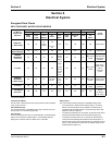
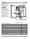
Wiring Diagram Sequence of
Operation
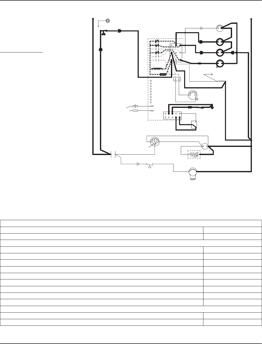
SELF-CONTAINED MODELS
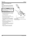
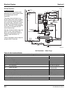
Initial Start-Up or Start-Up After
Automatic Shut-Off
1. WATER PURGE
Before the compressor starts, the
water pump and water dump
solenoid are energized for 45
seconds to purge old water from the
ice machine. This ensures that the
ice-making cycle starts with fresh
water.
The harvest valve(s) is also
energized during the water purge. In
the case of an initial refrigeration
start-up or auto shut-off, it stays on
for an additional
5 seconds (50 seconds total).
When Used - The air compressor
energizes for the last 10 seconds of
the cycle.
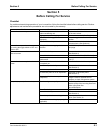
Self-Contained — Water Purge
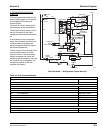
Table 6-1. Self-Contained Models
1. Water Purge (45 Seconds)
Toggle Switch ICE
Bin Switch Closed
Control Board Relays
#1 Water Pump ON
#2 Harvest Valve (Left) ON
#3 Harvest Valve (Right) ON (When Used)
#4 Air Compressor 35 sec. OFF / 10 sec. ON
#5 Water Inlet Valve OFF
#6 Water Dump Valve ON
#7 Contactor Coil Open / OFF
#7A Compressor OFF
#7B Condenser Fan Motor OFF
Safety Controls (Which could stop ice machine operation)
High Pressure Cut-Out Closed
Main Fuse (On Control Board) Closed
SV3137-2
(89)
(55)
(88)
High
Pressure
Cutout
Control Board
L1
Ground
(2)
(6)
(5)
(1)
(7)
(4)
L2 or N
Water Valve
Harvest Valve
(20)
(21)
(22)
(61)
Dump Valve
Water Pump
(60)
(76)
(81)
(75)
(77)
(80)
(57)
(98)
(58)
(59)
(42)
Ice Thickness
Probe
Water Level Probe
Trans.
Fuse (7a)
L2
Terminates at
Pin Connection
(99)
Contactor Coil
(56)
Air Compressor
(26)
(25)
Low DC
Voltage
Plug
Bin Switch
Clean
OFF
ICE
(2)
(1)
(6)
(8)
(9)
(74)
Compressor
Run Capacitor
(Red)
(Yellow)
Fan Motor
PTCR
(45)
(46)
(50)
(51)
(85)
Overload
(Black)
(86)
Fan Cycle
Control
L1
Contactor
Contacts
Run Capacitor