


10
FULL OVERLAY PANEL INSTALLATION INSTRUCTIONS
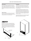
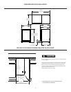
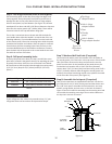
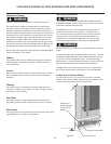
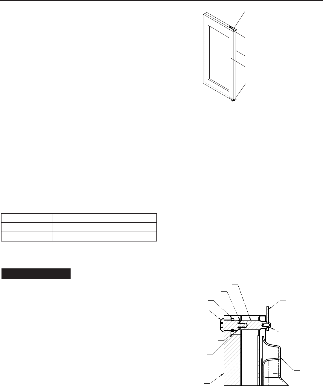
Step 5: Drill hinge clearance holes in overlay panel
Set the overlay panel on the door front, align the edges, and
clamp together. Clamp the panel rmly but be careful not to
damage the door or the panel. Mark center of hinge adapter
hole on wood panel, top and boom. (See Figure 10.) Remove
wood panel from door and drill 5/16” (8mm) diameter clearance
holes into the overlay panels 3/4” (20mm) deep. These will be
clearance holes for the top and boom hinge pins.
This is also a convenient me to locate and drill the holes for
your handle. Most oen the handle is to match that of the sur-
rounding cabinetry. If your handle aaches from the back-side
of the custom panel, locate the mounng holes while the panel
is aached to the door and cabinet. Aer the panel is removed
from the door, drill the mounng holes from the front, to the
recommended diameter of the handle manufacturer. Counter
bore the back-side of the panel so the screw heads do not inter-
fere with the surface of the door.
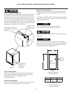
Step 6: Drill panel mounng holes
Re-clamp the panel to the door per step 5 and drill the screw
pilot holes, located in the gasket channel, for aaching the over-
lay panel to the door. Select the size of the hole from Table B.
Be careful not to drill the pilot holes through the overlay panel,
(1/2” (12.7mm) deep for 3/4” (19mm) and 5/8” (15.7mm)
panels ).
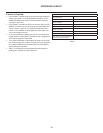
Material Type Pilot Hole for #8 Wood Screw
Hardwood 1/8” (3.2mm) Diameter. Pilot Hole
Sowood 7/64 (2.8mm) Diameter. Pilot Hole
If your refrigerator has a door lock proceed to Step 7. If your
refrigerator does not have a door lock proceed to Step 9.
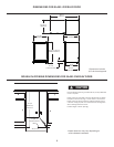
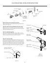
Step 7: Mark and drill lock hole (if required)
Locate and mark with a pencil the locaon of the lock hole on
the overlay panel, this is the hole in the top corner of the handle
side of the door. Remove the clamp and remove the overlay
panel from the door. On the backside of the panel where you
marked the lock locaon drill a 13/16” (20.5mm) diameter
counter bore 7/16” (11.0mm) deep into the overlay panel. Drill a
15/32” (12.0mm) diameter hole through the overlay panel cen-
tered on the counter bore being careful not to splinter the wood
on the face side of the panel. (See Figure 11).
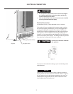
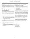
Step 8: Assemble the lock parts (if required)
Two (2) lock extensions are supplied with the lock. Use the lon-
ger extension for a 3/4” thick overlay panel and the shorter one
for a 5/8” thick panel. Assemble the lock extension, cam stop
washer, spring washer, and set screw to the lock as shown in
Figure 11 and 12. Install this assembly into the overlay panel and
secure with the retaining nut using a 15mm socket. Make sure
the key slot in the lock is vercal.
Overlay
panel
Door
Top hinge
adapter bracket
Hole in hinge
adapter bracket
Hole in bottom
hinge adapter bracket
NOTE
SECTION A-A
SCALE 1 : 1
LOCK
NUT
BRASS EXTENSION
CAM
PHILLIPS SCREW
13/16 COUNTER
BORE 7/16 DEEP
15/32 HOLE
3/4 INCH
WOOD PANEL
SPRING WASHER
INNER
DOOR
Figure 11
Figure 10
Glass door
shown
Table B