


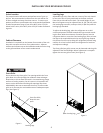
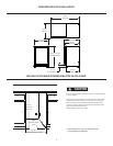
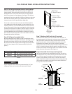
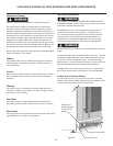
Door should be
parallel to top
and sides of
refrigerator.
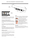
FULL OVERLAY PANEL INSTALLATION INSTRUCTIONS
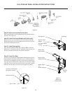
Step 1: Verify door alignment
Verify that the door is aligned with the cabinet prior to fabricat-
ing the custom panel. Failure to do so could result in mis-align-
ment of the custom panel with the hinge bracket. If alignment is
necessary the door may be adjusted by loosening the 2 screws
which secure the hinge adapter brackets on the top and boom
of the door and adjusng the door side to side. Use a 5/32” allen
wrench for this procedure. (See Figure 8 below). When nished
aligning the door, ghten the screws securely.
Hinge adapter brackets lo-
cated on the top and boom
of the door.
Remove the top
hinge pin to re-
move the door.
Step 2: Remove door
Remove the top hinge pin from the hinge with an 1/8” allen
wrench. Remove the door by angling the top of the door out-
ward and liing the door o the boom hinge.
(See detail in Figure 8).
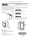
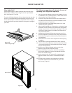
Step 3: Remove gasket
Lay the door on its front being careful not to scratch it. Remove
the door gasket by peeling up and out of the channel.
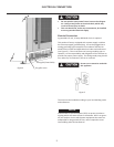
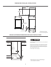
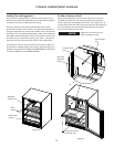
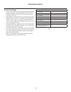
Step 4: Cut overlay panel
Depending on the refrigerator model cut the overlay panel to
the dimensions shown. Use Figure 9 and Table A for glass door
models.
The non-glass, solid door, will use the same height and width di-
mensions as the glass door. The center of the solid door custom
panel will not be removed.
For overlay with lock opon panel thickness to be
3/4” (19mm) maximum to 5/8” (16mm) minimum.
Weight of the overlay panel should not exceed 20 pounds (9.1
kilograms).
9
For the door to close properly, it is necessary to maintain a
minimum space of 9/32” (7mm) between the door and cabinet
ange, (see Figure 8). This space can be adjusted by adjusng
the top and boom hinge adapter brackets.
9/32”
(7mm)
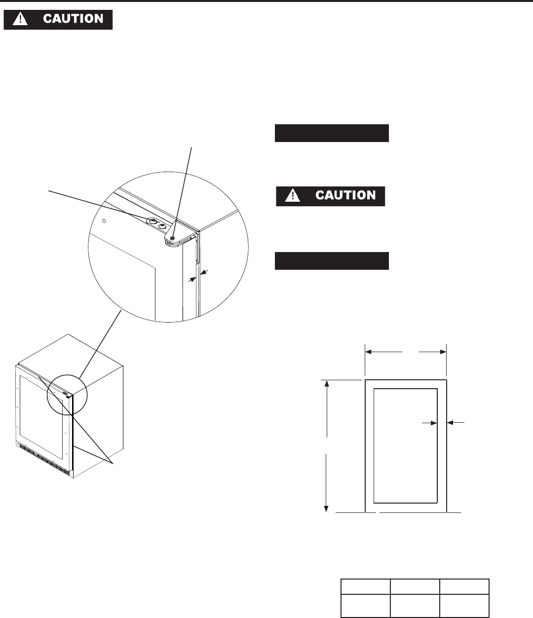
Model W H
6GARM
23-5/8”
(60.0cm)
30-3/8”
(77.17cm)
Glass Door Models and
Solid Door Models
W
H
Overlay
panel
dimensions
2-1/32”
(38.77cm)
minimum
Glass Door Models and
Solid Door Models
NOTE
NOTE
Figure 8
Figure 9
Table A