


10
ENGLISH
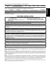
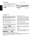
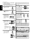
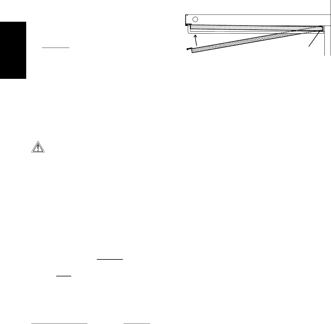
Figure 2-12 - Crumb trays
Swing outside
edge of tray
up and into
place
Place inside
edge of tray on
retainer bracket
SECTION 2 - INSTALLATION
VI. ELECTRICAL SUPPLY
WARNING
Authorized supplier personnel normally accomplish
the connections for the ventilation system, electric supply,
and gas supply, as arranged by the customer. Following
these connections, the factory-authorized installer can
perform the initial startup of the oven.
NOTE: The electric supply installation must satisfy the
requirements of the appropriate statutory authority, such as the
National Electrical Code (NEC), ANSI/NFPA70, (U.S.A.); the
Canadian Electrical Code, CSA C22.2; the Australian Code
AG601; or other applicable regulations.
NOTE: The electric supply connection must meet all national
and local electrical code requirements.
Check the oven serial plate before making any electric supply
connections. Electric supply connections must agree with data
on the oven serial plate. The location of the serial plate is shown
in Figure 1-1 (in Section 1,
Description).
A fused disconnect switch or a main circuit breaker (customer
furnished)
MUST be installed in the electric supply line for each
oven cavity. It is recommended that this switch/circuit breaker
have lockout/tagout capability.
The supply conductors must be of the size and material (cop-
per) recommended. Refer to the wiring diagram inside the
machinery compartment of the oven. Electrical specifications
are also listed on the oven's serial plate and in Table 1-4,
Electrical Specifications (in Section 1, Description).
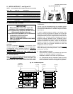
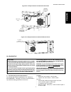
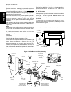
The oven requires a ground connection to the oven ground
screw. For gas ovens, the ground screw is located in the
electrical junction box (see Figure 2-13). For electric ovens, the
ground screw is located inside the side compartment of the
oven (see Figure 2-14). If necessary, have the electrician supply
the ground wire. Do NOT use the wiring conduit or other piping
for ground connections!
V. FINAL ASSEMBLY
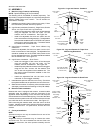
1. Install the crumb trays underneath the conveyor as shown
in Figure 2-12. First, place the inside edge of the tray onto
the retainer (shown in Figure 2-9). Then, swing the outside
edge of the tray up and into place.
2. Press the conveyor end stop and rear stop down over the
edge of the conveyor frame. See Figure 1-1 (in Section 1,
Description).
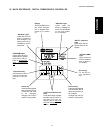
A. Additional Information - Gas Ovens
Incoming electrical power lines are fed through the strain-
relief fitting, shown in Figure 2-13. The electrical supply
connections are made inside the electrical junction box.
The power lines then connect to the oven circuits through
safety switches located inside the machinery compart-
ment and each blower motor compartment. These switches
interrupt electric power to the oven when the Machinery
Compartment Access Panel is opened, OR when either of
the blower or rear shrouds is removed.
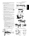
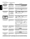
B. Additional Information - Electric Ovens
A 2" (51mm) dia. cutout in the back wall of the machinery
compartment provides access to the electrical supply
connections. The actual wiring connections are made at
the terminal block located inside the side compartment of
the oven.
Using flexible cables for the electric power supply
conductors requires a 2" (51mm) strain-relief fitting (not
furnished with the oven) to enable safe access to the
terminal block.
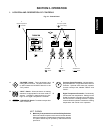
C. Connection
Refer to the wiring diagram inside the machinery
compartment of the oven to determine the correct
connections for the electrical supply lines. Connect the
supply as indicated on the wiring diagram.
CAUTION
The terms of the oven's warranty require all start-ups, conver-
sions and service work to be performed by a Middleby Marshall
Authorized Service Agent.