


8
ENGLISH
SECTION 2 - INSTALLATION
IV. ASSEMBLY
A. Base Pad, Legs, Casters, and Stacking
NOTE: Optional Stacking Lift Kit (P/N 30580)
The Stacking Lift Kit, P/N 30580, is available separately. This
Kit provides a complete lift adapter set, specifically designed for
stacking PS500 Series oven cavities. The Kit includes an
instructional videotape.
1. Install the top panels in place on the top oven cavity. Follow
the instructions provided with the top panels.
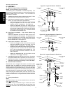
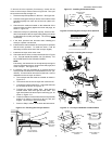
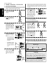
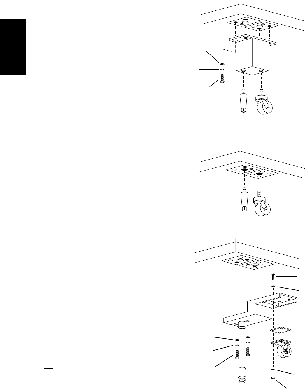
2a. Legs/Casters Installation (Standard) - Single Ovens, Double
Ovens, and Triple Ovens with Leg Extensions
Install one leg extension to each corner of the base pad
using the supplied 1/2"-13x1-1/4" bolts, 1/2" flat
washers, and 1/2" lockwashers. See Figure 2-4.
Install one adjustable foot and one caster into the
holes on the bottom of the leg extension. The adjustable
foot should be installed into the OUTSIDE hole (closest
to the front or rear face of the oven). The caster should
be installed into the INSIDE hole.
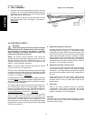
2b. Legs/Casters Installation - Triple Ovens Without Leg
Extensions
Install one adjustable foot and one caster into the 3/4"
holes on the bottom of the base pad. The adjustable foot
should be installed into the OUTSIDE hole (closest to the
front or rear face of the oven). The caster should be installed
into the INSIDE hole. See Figure 2-5.
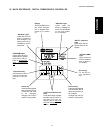
2c. Legs/Casters Installation - Quad Ovens
Install one outrigger to each corner of the base pad
using the supplied 1/2"-13x1-1/4" bolts, 1/2" flat
washers, and 1/2" lockwashers. See Figure 2-6.
Install the spacer plates and casters onto the outriggers
using the 3/8"-16x1" screws, 3/8" flat washers, and
3/8"-16 hex nuts supplied in the Installation Kit. The
two locking casters should be installed on the front
side of the oven.
Install the adjustable feet into the holes on the
underside of the outrigger assembly.
3. Install the base pad onto the lower oven cavity. Check that
the eyebolt welded onto the pad faces the rear of the oven.
4. Stack the oven cavities. If necessary, refer to the instructional
videotape provided with the Stacking Lift Kit (P/N 30580).
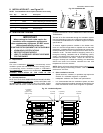
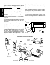
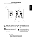
B. Restraint Cable Installation
Because the oven is equipped with casters, a restraint cable
assembly must be installed to limit the movement of the
appliance without depending on the connector and the quick
disconnect device or its associated piping. One end of the cable
is anchored to the eyebolt on the rear surface of the oven's base
pad, while the other is anchored to the wall. See Figure 2-7.
After connecting the restraint cable, move the oven to its final
location. Adjust the bottom (hex) sections of the feet so that the
casters are off the floor. For quad ovens, lock the two front
casters.
C. Conveyor Installation
NOTE
Split belt conveyors can only be installed from the end of the
oven
with the drive motor.
Single-belt conveyor assemblies may be inserted into either
end of the oven. If it is to be installed from the end of the oven
without the drive motor, the drive sprocket assembly must be
removed.
Figure 2-4 - Legs and Casters - Standard
Front or Rear
of oven
Left or Right Side
of oven
1/2"
flat washer
Foot uses OUTSIDE
hole (closest to front
or rear of oven)
Caster
uses
INSIDE
hole
Figure 2-6 - Legs and Casters for Quad Oven
1/2"
lock
washer
1/2"-13 x 1-1/4"
hex screw
1/2" flat
washer
1/2" lock
washer
1/2"-13 x 1-1/4"
hex screw
3/8"-16 x 1"
hex screw
3/8" flat
washer
Locking casters:
FRONT of oven
Non-locking
casters:
REAR of oven
Front or Rear
of oven
Left or Right Side
of oven
Adjustable
foot
3/8"-16
hex lock nut
3/8" flat
washer
Figure 2-5 - Legs and Casters for Triple Oven
Without Leg Extensions
Spacer
plate
Front or Rear
of oven
Left or Right Side
of oven
Foot uses OUTSIDE
hole (closest to front
or rear of oven)
Caster
uses
INSIDE
hole
Locking
caster
shown
Outrigger