


11
ENGLISH
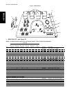
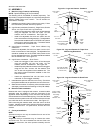
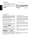
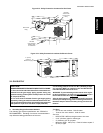
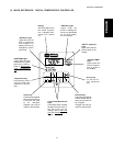
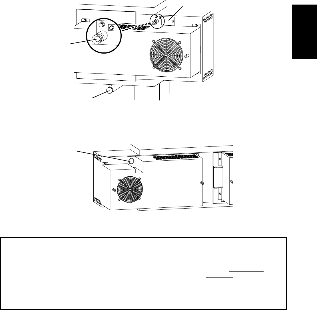
Figure 2-13 - Utility Connection Locations for Gas Ovens
Electrical
Junction Box
One per oven
cavity
Gas Inlet
One per Single,
Double, Triple,
or Quad Oven
VII. GAS SUPPLY
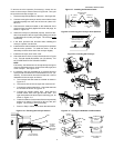
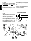
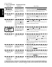
Figure 2-14 - Utility Connection Locations for Electric Ovens
2" (51mm)
cutout for
electrical supply
A. Gas Utility Rough-In Recommendations
The following gas system specifications are STRONGLY
RECOMMENDED. Deviating from these recommendations
may affect the baking performance of the oven.
Gas Meter
One or two oven cavities: 750 cfh meter
Three or four oven cavities: 1200 cfh meter
Gas Line
DEDICATED LINE from the gas meter to the oven
2-1/2" (63.5mm) pipe for natural gas
2" (50.8mm) pipe for propane
Maximum length: 200' (61m). Each 90° elbow equals 7'
(2.13m) of pipe.
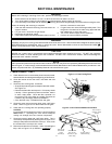
CAUTION
DURING PRESSURE TESTING NOTE ONE OF THE FOLLOWING:
1. The oven and its individual shutoff valve must be discon-
nected from the gas supply piping system during any
pressure testing of that system at test pressure in excess
of 1/2 psi (3.45 kPa).
2. The oven must be isolated from the gas supply piping
system by closing its individual manual shutoff valve dur-
ing any pressure testing of the gas supply piping system at
test pressure equal to or less than 1/2 psi (3.45 kPa).
3. If incoming pressure is over 14 W.C. (35mbar), a sepa-
rate regulator MUST be installed in the line BEFORE the
individual shutoff valve for the oven.
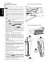
WARNING: To prevent damage to the control valve regula-
tor during initial turn- on of gas, it is
very important to open
the manual shutoff valve
very slowly.
After the initial gas turn-on, the manual shutoff valve must
remain open except during pressure testing as outlined in
the above steps or when necessary during service main-
tenance.
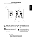
SECTION 2 - INSTALLATION
Strain-relief
fitting