


9
ENGLISH
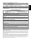
SECTION 2 - INSTALLATION
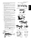
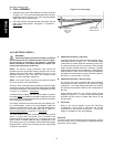
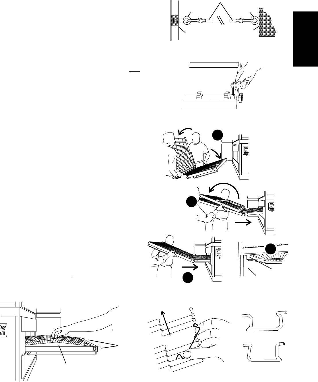
Figure 2-10 - Checking the conveyor tension
3-4" (75-100mm)
vertical deflection
Conveyor
tension
adjustment
screws (idler
end only)
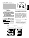
Eyebolt in
base pad
Rear surface
of oven base
pad
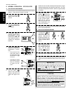
Restraint cable
assembly
3/4 (19mm)
eyebolt
Wall of
structure
Figure 2-7 - Installing the Restraint Cable
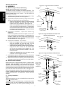
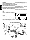
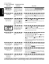
Figure 2-9 - Inserting the Conveyor
1
2
3
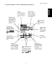
Figure 2-8 - Removing the Conveyor Drive Sprocket
Loosen conveyor collar
set screw, then pull
sprocket straight out
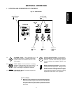
Figure 2-11 - Conveyor and Master Link Orientation
Direction
of travel
Outside master link
orientation
CORRECT
master link
position
Incorrect
master link
position
To remove the drive sprocket (if necessary), loosen the set
screw on the conveyor collar as shown in Figure 2-8. Then, pull
the sprocket assembly straight out.
1. Lift the conveyor and position it in the oven. See Figure 2-9.
2. Continue moving the conveyor into the oven until the frame
protrudes equally from each end of the oven (about 18"/
457mm).
3. Check that the retainers located on the underside of the
conveyor frame rest firmly against the lower end plugs, as
shown in Figure 2-9.
4. When the conveyor is positioned properly, check for free-
dom of movement of the conveyor belt by pulling it for about
2-3 feet (60 to 90 cm) with your fingers. The conveyor
must
move freely.
5. If the drive sprocket was removed when installing the
conveyor, replace it at this time.
6. Install the drive chain between the conveyor drive sprocket
and the motor sprocket. To install the chain, it will be
necessary to lift the drive end of the conveyor slightly.
7. Install the conveyor drive motor cover.
8. Check the tension of the conveyor belt as shown in Figure
2-10. The belt should lift between 3-4" (75-100mm). DO
NOT OVERTIGHTEN THE CONVEYOR BELT.
NOTE:
If necessary, the belt tension can be adjusted by turning the
conveyor adjustment screws, located at the idler (right) end
of the conveyor. See Figure 2-10.
9. If necessary, links can be added to or removed from the
conveyor belt to achieve the correct deflection of 3-4" (75-
100mm). If links must be removed from the belt, it can be
reattached to the conveyor as follows:
a. The conveyor belt links must be oriented as shown in
Figure 2-11.
b. The smooth side of the conveyor belt must face UP.
c. Connect the inside master links. Check that the links
are oriented as shown in Figure 2-11.
d. Connect the outside master links. Note that the
outside master links have right and left sides. The
right-side master link has an open hook facing you, as
shown in Figure 2-11.
e. Check for freedom of movement of the conveyor belt by
pulling it for about 2-3 feet (60 to 90 cm) with your
fingers. The conveyor
must move freely.
f. Return to Step 8, above, to re-check the belt tension.
Inside master link
orientation
Retainer
4
End plug