


22
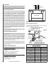
Electrical Connections:
* The breaker supplying electricity to the fireplace must be turned off at the
electrical panel before any connections are made at the fireplace.
* The wire supplying the fireplace should be a minimum of 14 gage and
provide 120 Volts at 60 hz.
* The fireplace must be grounded in accordance with local electrical
codes or, in the absence of local codes, with the National Electrical
Code or ANSI/NFPA 70 - latest edition.
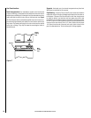
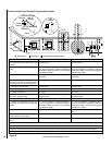
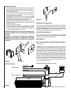
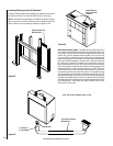
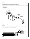
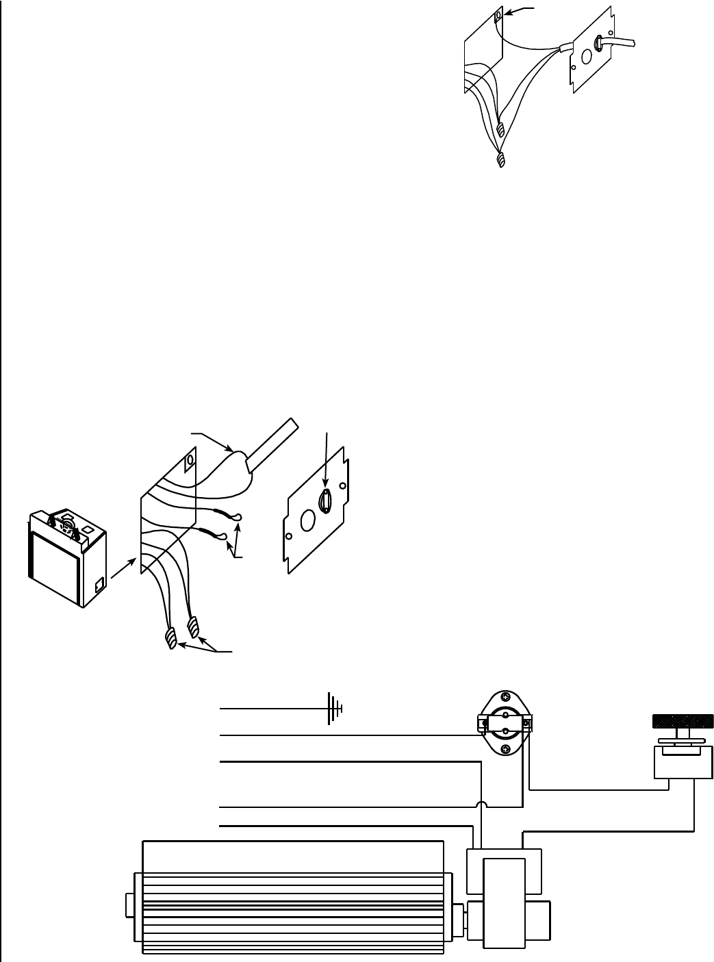
* The electrical box is located at the right rear of the fireplace (see
Figures
29 and 30). Remove the cover, loosen the wire clamp A and feed the
household supply line through the clamp and retighten clamp.
* Connect the supply ground wire to the green screw B.
* Remove the wire nut C from the black wires coming from the fireplace
and join these wires to the black supply wire reusing the wire nut.
Repeat for white wires.
* Reinstall the cover to the fireplace.
* If a wall-mounted burner on/off switch or thermostat is to be used,
the wires running from the switch or thermostat should be routed to
the left side of the fireplace. The wire should be fed through the gas
line supply hole along the gas line to the valve.
CAUTION: Label all wires prior to disconnection when servic-
ing controls. Wiring errors can cause improper and dangerous
operation.
ATTENTION: Au moment de l'entretien des commandes,
étiquetez tous les fils avant de les débrancher. Des erreurs
de cáblage peuvent entraîner un fonctionnement inadéquat et
dangereux.
Wall-Mounted Fan Speed Control:
If desired, a wall-mounted fan speed control can be installed. The breaker
supplying electricity to the fireplace must be turned off at the electrical
panel before any connections are made. The loop of wire with the label
attached (E in Figure 29) may be cut and the wire leads from the wall-
mounted speed control connected to each end of the cut wire.
Optional Heat Ducting System:
The remaining red and white wires with capped ends (wires D in Figure
29) are for the optional Forced Air Heating System. See the instructions
provided with the system for installation details.
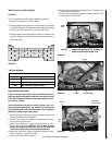
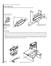
Blower Removal:
Disconnect the power supply at the household electrical panel prior to
blower removal. The blower can be accessed through the lower door on
the fireplace face.
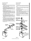
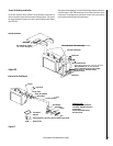
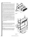
See Figure 31 for the fan wiring diagram, for reference. The blower is
located at the rear of the open area beneath the firebox. (During instal-
lation of the fireplace, if the gas line was fed in from the right side it will
now need to be removed). To remove the blower, disconnect the wiring
by pulling the two spade connectors loose at the blower motor. The
blower rests on two pins - one located at each end of the blower. Grasp
the blower assembly at each end and pull the blower forward off the two
pins. (If the blower assembly is pulled from the center, it may distort the
assembly). The blower can then be carefully pulled out from under the
fireplace. To install the blower repeat the steps in the reverse order. There
is a rubber grommet at each end of the blower assembly which slides
over the pins supporting the blower. Make sure these grommets are in
place when reinstalling the blower.
Figure 29
Figure 30
Figure 31
L
a
b
e
l
L
a
b
e
l
D
A
C
E
B
Fan Wiring Diagram
Green (Ground)
Snap Switch (Contacts Close When Fireplace is Hot)
Black (Hot)
From Power Source
Speed Control
White (Neutral)
Black
Black
Red
White
Blower
To Optional Heat Duct Fan
NOTE: DIAGRAMS & ILLUSTRATIONS ARE NOT TO SCALE.