


28
NOTE: DIAGRAMS & ILLUSTRATIONS ARE NOT TO SCALE.
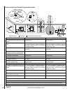
Wiring of the Forced Air System Continued:
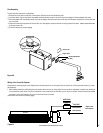
2. Remove the cover over the electrical box at the right lower rear of the
fireplace. Run sheathed wire from the fireplace electrical box to the
switch box and from the switch box to the fan box. Install the wire
clamp in the unused knock-out hole in the fireplace electrical box
cover. Run the end of the sheathed wire through this wire clamp. In the
electrical box are a white wire and a red wire with clear caps on their
ends. Remove these caps and join the red wire and black wire with
the wire nuts provided. Also join the white wire from the fireplace with
the white wire from the sheathed wire using the wire nuts provided.
Fasten the ground wire from the sheathed wire to the green grounding
screw in the electrical box. When the fireplace gets up to temperature,
a heat activated switch will close and allow electricity to flow to the
red wire.
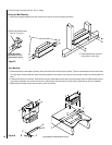
3. At the switch box, cut the black sheathed wire, strip back the insula
-
tion and join each end (with the wire nuts provided) to a lead from the
speed control. It does not matter which lead from the speed control is
fastened to which black wire. After making these connections, roll the
connectors and wire into the switch box. Two different colors of covers
and knobs come with the kit. Select the cover desired and fasten the
speed control and cover to the box with the screws supplied. Push
the desired knob onto the shaft of the speed control.
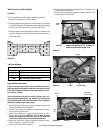
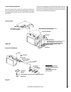
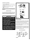
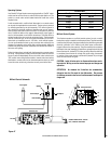
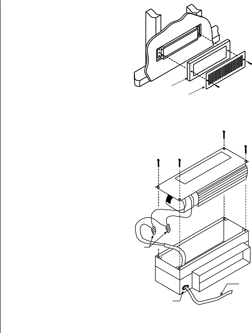
4. Remove the four screws holding the fan to the fan box and lift fan out
of the fan box (see Figure 43). Feed the sheathed wire A through the
wire clamp B. Remove the insulation from the sheathed wire and the
two wires coming from the fan motor. Join together using the wire
nuts provided the black wire from the motor and the black sheathed
wire. Also join the two white wires. Fasten the ground wire to the green
grounding screw inside the fan box. Reinstall the fan in the fan box
using the four screws.
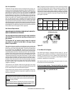
Notes:
The speed of this forced air system fan can be controlled by the speed
control that is installed with it. The speed control also has an off position.
This fan is energized only when the fireplace is up to temperature. It will
also shut off automatically when the fireplace cools down.
To maximize hot air distribution, this forced air system can be used in
conjunction with the Whole Home Comfort System described in this
manual.
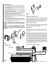
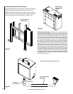
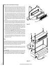
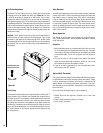
Grill Installation: The Grill that covers the fan box is secured with the
two white-headed screws provided. When the fan box is mounted in a 2”x
4” framed wall the box will extend past the sheetrocked wall into the room.
In these installations the Grill spacer should be used (see Figure 42).
Figure 42
Figure 43
Grill Spacer
Grill
C
B
A