


FX1N Series Programmable Controllers Outputs 6.
6-5
1
2
3
4
5
6
7
8
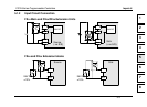
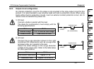
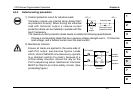
6.2.2 Output circuit configuration
An internal protection circuit for the relays is not provided in the relay output circuit for this
product. It is recommended to use inductive loads with built-in protection circuits. When using
loads without built-in protection circuits, insert an external contact protection circuit, etc. to
reduce noise and extend the product life.
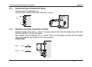
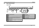
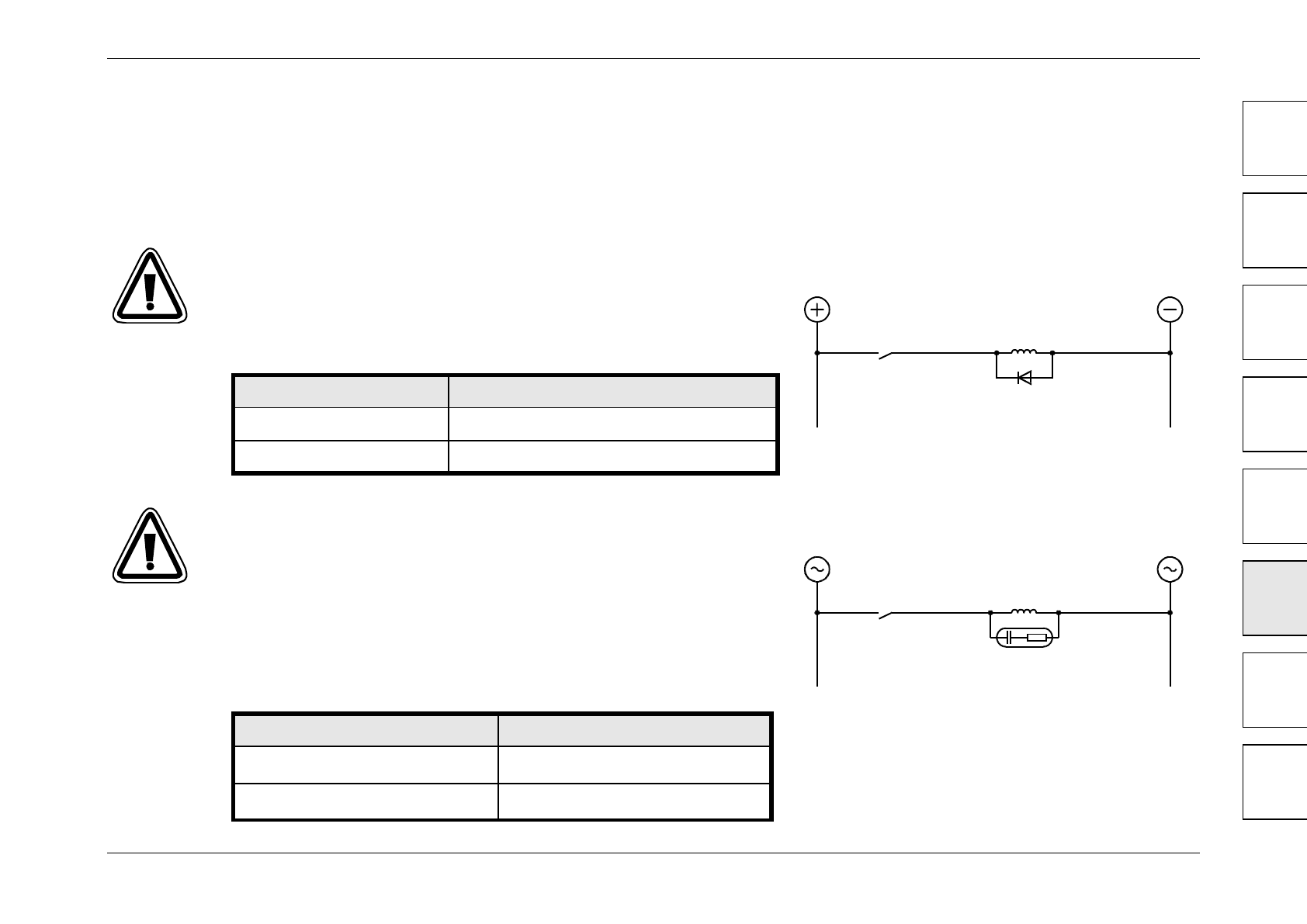
1) DC load
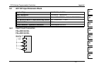
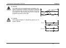
2) AC load
Connect a diode in parallel with the load.
The diode (for commutation) must comply with the
following specifications.
Connect the surge absorber shown to the right
(combined CR components such as a surge killer
and spark killer, etc.) parallel to the load.
Select the rated voltage of the surge absorber
suitable to the output used. Refer to the table below
for other specifications.
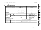
Item Guide
Reverse voltage 5 to 10 times the load voltage
Forward current Load current or more
Inductive load
PLC output
contact
Diode
(for commutation)
Item Guide
Electrostatic capacitance
Approx. 0.1
μ
F
Resistance value
Approx. 100 to 200
Ω
Inductive load
Surge
absorber
PLC output
contact