


Terminal layouts 2.
2-1
1
2
3
4
5
6
7
8
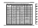
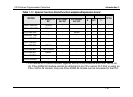
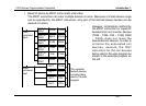
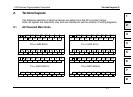
2. Terminal layouts
The following selection of terminal layouts are taken from the FX
1N
product range.
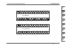
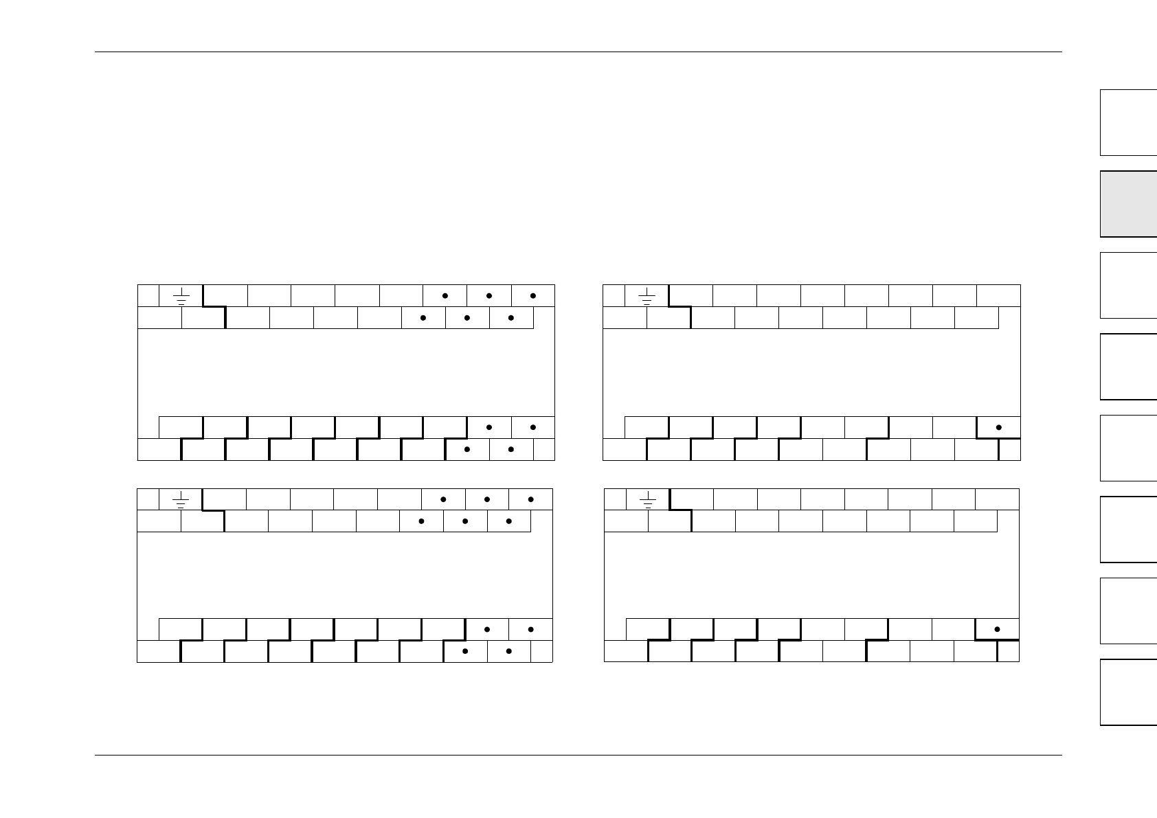
Note: All layouts are schematic only and are intended to aid the creation of wiring diagrams.
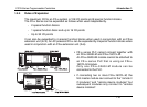
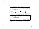
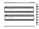
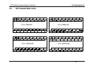
2.1 AC Powered Main Units
S/S X1
N X0 X4
FX
1N
-14MR-ES/UL
X5
0V Y0 Y1 Y2 Y3
X3
X2
24V
COM0 COM1 COM3COM2
L
X7
X6
Y4
COM4 COM5
Y5
S/S X1
N X0 X4
FX
1N
-24MR-ES/UL
X5
0V Y0 Y1 Y2 Y3
X3
X2
24V
COM0 COM1 COM3COM2
L
X7
X6
Y5
COM4
X12
X13X11
X10
X15
X14
Y6
Y4
Y10
Y7 Y11
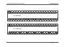
S/S X1
X0 X4
X5
0V Y0 Y1 Y2 Y3
X3
X2
24V
X7
X6
Y5
X12
X13X11
X10
X15
X14
Y6 Y10
Y7 Y11+V0 +V1 +V2 +V3 Y4 +V4
FX1N-24MT-ESS/UL
N
L
S/S
X1
X0 X4
X5
0V
Y0 Y1 Y2 Y3
X3
X2
24V
+V0 +V1 +V3+V2
X7
X6
Y4
+V4 +V5
Y5
FX
1N
-14MT-ESS/UL
NL
FX1N Series Programmable Controllers