


Introduction 1.
1-1
1
2
3
4
5
6
7
8
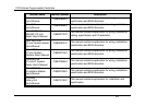
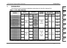
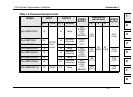
1. Introduction
This manual covers hardware installation instructions for the FX
1N
Series PLC.
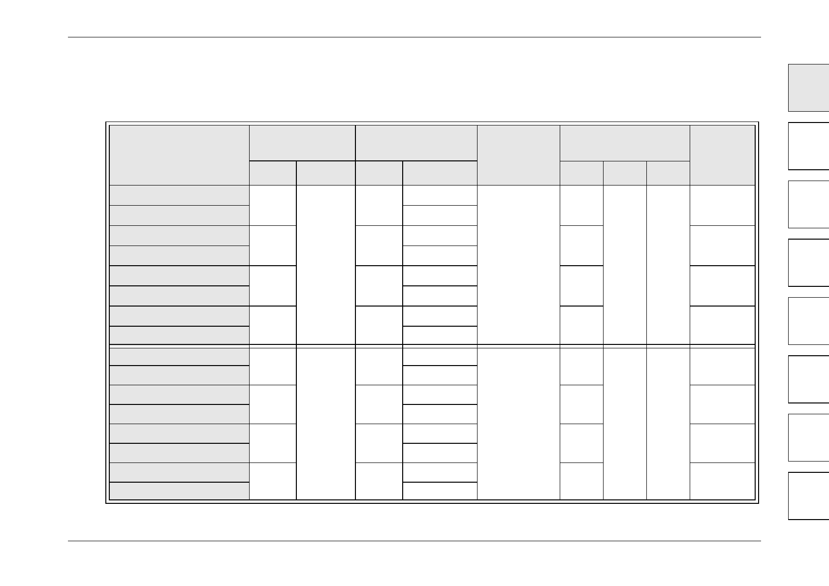
Note: Occupied points are shown in brackets for input and outputs.
Table 1.1: FX
1N
Main Modules
MODEL
INPUT OUTPUT
POWER
SUPPLY
DIMENSIONS
mm (inches)
WEIGHT
kg (lbs)
QTY TYPE QTY TYPE
W H D
FX
1N
-14MR-ES/UL
8
24V DC
Sink/
Source
6
(8)
Relay
100-240 VAC
+10%
-15%
50/60Hz
90
(3.55)
90
(3.55)
75
(2.96)
0.45
(0.99)
FX
1N
-14MT-ESS/UL
Transistor
FX
1N
-24MR-ES/UL
14
(16)
10
(16)
Relay
90
(3.55)
0.45
(0.99)
FX
1N
-24MT-ESS/UL
Transistor
FX
1N
-40MR-ES/UL
24 16
Relay
130
(5.12)
0.65
(1.43)
FX
1N
-40MT-ESS/UL
Transistor
FX
1N
-60MR-ES/UL
36
(40)
24
Relay
175
(6.89)
0.80
(1.76)
FX
1N
-60MT-ESS/UL
Transistor
FX
1N
-14MR-DS
8
24V DC
Sink/
Source
6
(8)
Relay
12V DC
-15%
to
24V DC
+20%
90
(3.55)
90
(3.55)
75
(2.96)
0.45
(0.99)
FX
1N
-14MT-DSS Transistor
FX
1N
-24MR-DS
14
(16)
10
(16)
Relay
90
(3.55)
0.45
(0.99)
FX
1N
-24MT-DSS Transistor
FX
1N
-40MR-DS
24 16
Relay
130
(5.12)
0.65
(1.43)
FX
1N
-40MT-DSS Transistor
FX
1N
-60MR-DS
36
(40)
24
Relay
175
(6.89)
0.80
(1.76)
FX
1N
-60MT-DSS Transistor
FX1N Series Programmable Controllers