


FX1N Series Programmable Controllers Installation Notes 3.
3-3
1
2
3
4
5
6
7
8
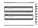
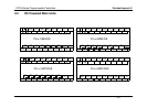
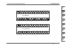
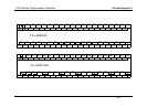
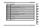
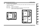
Table 3.1 : Features table
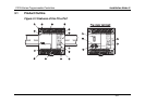
1
Top cover
2
Direct mounting holes (4.5 mm <0.17"> diameter)
3
I/O terminal block securing screws
4
Input terminals (24V DC) and power supply terminals
5
Input LED status indicators
6
Expansion port cover
7
PLC status indicators (POWER, RUN, ERROR)
8
Output LED status indicators
9
DIN rail mounting clip
10
Output terminals and power supply source terminals
11
Optional equipment connector
12
Expansion port
13
Run/Stop switch
14
Programming port
15
Variable analog potentiometers. Upper pot, D8030 read from VR1. Lower pot D8031
read from VR2