


11
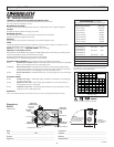
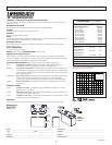
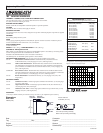
Engineering Data - HRV Model RNC120D
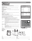
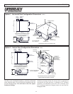
FRESH AIR
FROM
OUTSIDE
STALE
AIR TO
OUTSIDE
STALE AIR
FROM BUILDING
FRESH AIR
TO BUILDING
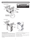
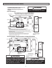
BOTTOM VIEW FOR HORIZONTAL MOUNT
SERVICE CLEARANCE FROM BOTTOM
OF UNIT IS MINIMUM 3’0”
SIDE VIEW FOR HORIZONTAL MOUNT
ALL DUCT COLLARS
ARE 5” DIAMETER
Connect drain hose to spout located in door.
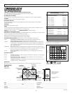
9-1/8”
(232 mm)
25 1/8”
(637 mm)
22”
(559 mm)
HANGING STRAPS
STALE AIR
TO OUTSIDE
FRESH AIR
FROM OUTSIDE
ACCESS DOOR
STALE AIR
FROM BUILDING
FRESH AIR
TO BUILDING
Option 1 - Horizontal Duct Configuration Dimensions inches
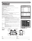
FRESH AIR
FROM
OUTSIDE
STALE
AIR TO
OUTSIDE
STALE AIR
FROM BUILDING
FRESH AIR
TO BUILDING
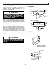
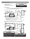
SIDE VIEW FOR VERTICAL MOUNT
SERVICE CLEARANCE FROM BOTTOM
OF UNIT IS MINIMUM 3’0”
TOP VIEW FOR VERTICAL MOUNT
Connect drain hose to the two field installed
spouts located on the bottom of the unit.
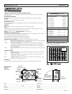
9-1/8”
(232 mm)
25 1/8”
(637 mm)
22”
(559 mm)
HANGING STRAPS
STALE AIR
TO OUTSIDE
FRESH AIR
FROM OUTSIDE
ACCESS DOOR
STALE AIR
FROM BUILDING
FRESH AIR
TO BUILDING
“L” BRACKETS
(not included)
May be installed if
wall mounting is
desired for the
vertical installation.
ALL DUCT COLLARS ARE
5” (127 mm) DIAMETER
Option2-Vertical Duct Configuration Dimensions inches
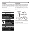
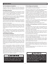
The HRV can be installed horizontally or vertically as illustrated
on the following pages. The unit should be suspended using the
provided hanging straps. The unit must be level for proper
condensate drainage.
Sufficient clearance below the access door is required for
servicing the air filters and core. A minimum of 25" (635mm)
clearance is recommended so the door can be removed. Four
PVC reinforced polyester hanging straps are provided for
hanging the HRV.