


25
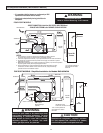
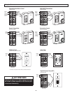
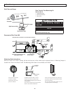
Air Flow Balancing
Place pitot tube a minimum of 18" from blower or elbows
Note: Duct connections may vary,
depending on model.
Outdoors
MAGNEHELIC
Pitot
tube
Magnehelic
gauge
M
A
GN
E
HELIC
Magnehelic
gauge
Pitot
tube
Additional dampers
may be required
Placement of Pitot Tube HRV
M
AGNEHELIC
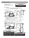
DUCT
AIR
FLOW
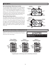
Pitot tube
High Pressure Side
Low Pressure Side
Magnehelic gauge
Pitot Tube and Gauge
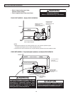
Pitot Tube Air Flow Balancing Kit
Part No. 99-167
1 - magnehelic gauge
1 - Pitot Tube and hose
1 - Carry Case
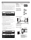
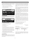
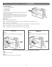
ATTENTION
Apply use of balancing dampers as
required.
Push and turn with slotted
screwdriver. Damper
automatically locks when
pressure is released.
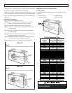
When connecting ductwork to the collar, take
note where screws are located. Screws should
be located no further
than 1/2” from outside edge of collar, so as not
to impede operation of the damper.
1/2”
Hard/Rigid
ducting
Insulated flexible
ducting
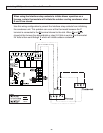
Installations where the HRV is ducted
directly to the return of a furnace may
require additional dampening on the fresh air
to building duct.
This is due to the high return static pressures
found in some furnace installations.
Balancing Collar Instructions
Often the “Fresh Air to House” ducting will have the heaviest air flow which must be dampered down. A Balancing Damper is
located in the “Fresh Air to House” collar. The Balancing Collar feature is not available on all models.
NOTE
Graphic is for illustrative purposes only. Duct
connection ports may vary.