


21
Electrical
The HRV unit should be plugged into a standard designated (120VAC)
electrical outlet with a ground. The outlet should be serviced by a separate
15 amp/120V circuit. An extension cord should not be used with this
appliance. A qualified service technician should make any required
electrical connections.
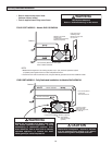
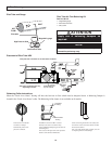
Remote Control Connections
Prior to connecting remote devices, it is advisable to run
self test on the HRV/ERV.
Low voltage connections between the remote controls, the dehumidistat, or
the fan timer should be made by a qualified service technician. Low voltage
wires from the remote controls are connected to the HRV micro-processor
board.
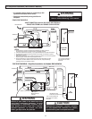
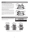
In order to prevent electric shock when cleaning
or servicing the HRV, it is extremely important to
confirm the polarity of the power line that is
switched by the safety (disconnect) switch. The
hot line (black) is the proper line to be switched.
To confirm the proper polarity, use a voltmeter
or test lamp to ensure there is no power after
the switch when the door is open. Check
between that point and ground (on the cabinet).
Always make sure that the HRV is properly
grounded.
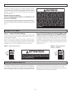
WARNING
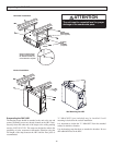
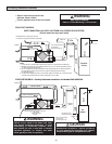
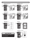
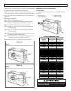
Figure 1 - Factory DIP Switch Settings
The factory setting of the DIP switches (located on the circuit board)
provides continuous low speed ventilation. Optional Remote Controls will
initiate high speed ventilation.
Remote controls with an ON/OFF switch (refer to "Remote Control
Devices" in this manual) will shut the entire system down when the remote
control is in the OFF position. Changing the remote control from OFF to
STANDBY can be achieved by Setting the DIP Switch as per Figure 2.
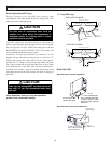
Figure 2-DIP Switch Settings for Standby (When using
a Remote Control Device that has an ON/OFF Switch)
This DIP Switch Setting can be adjusted when using a system control that
has an ON/OFF switch (refer to "Remote Control Devices" in this manual).
"STANDBY" is achieved when the Remote Control Switch is in the "OFF"
position. The Dehumidistat and Timers will initiate high speed ventilation
regardless of the "ON/OFF" switch position when this DIP switch
configuration is used.
Changing OFF to STANDBY
HS
REMOTE
DFR2
DFR3
ON
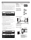
The ventilator automatically operates on its lowest speed when plugged in
or switched on. This setting is factory supplied from an autotransformer
with two selectable low speeds. To switch to a continuous medium low
speed, an installing contractor must interchange the red and blue wires from
the autotransformer inside the electrical box. Whether or not this change is
made, the HRV will only be able to access a single selected low speed.
High speed is available with the use of optional remote controls connected
to the appropriate terminals inside the electrical box.
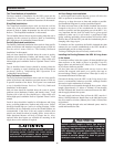
Increasing Low Speed to Medium Low
HS
REMOTE
DFR2
DFR3
ON
Figure 1 - Factory setting for OFF
Figure 2 - Contractor adjusted
setting for STANDBY
Figure 2 may not meet building code conformance
in certain geographical areas. Check with your
local building authority.
ATTENTION