


Index
IN-3
7510-A2-GB20-00 March 1997
R
rear panel, connections, 1-4
reset device, 6-4
revision numbers, 6-4
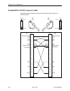
RJ48S network interface cable, C-5
RTS, request to send LED, 4-11
RXD, received data LED, 4-11
S
safety instructions.
See
Start-Up Instructions
saving option changes, 3-2
screen function keys, 2-6
screen work areas, 2-4
screens, for user interface, 2-3
self-test, 6-4
self-test results, 4-4
serial number, 6-4
software revision number, 6-4
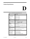
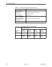
specifications, 1-1, D-1
start-up, ATI, 2-1
statistics, of network performance, 4-7
status
indicators on front panel, 1-3
network interface, 4-6
of DSU, 4-2– 4-3
test messages, 4-5
Status menu, 4-2, 4-6, 4-7, 4-8
switching screen areas, 2-7
system
device name field, 3-1
LEDs, 4-9
System and Test Status branch, 4-2
System Contact, 3-1
System Location, 3-1
System Name, 3-1
system name, 6-4
T
technical specifications, D-1
terminal port
direct connection, 2-1
options, A-7
test
DTE, 5-7
LED, 4-9
network, 5-3
status messages, 4-5
Test menu, 5-1, 5-3, 5-7, 5-9
testing, 4-1, 5-1
troubleshooting, 6-3
TXD, transmitted data LED, 4-11
U
user interface, 1-3
access, 2-1
async terminal, 2-1
V
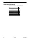
V.35 connector, C-3
V.54 sequences, 5-5
W
worksheets, option configuration, B-1