


PitcoSolsticeandSolsticeSupremeHighEfficiencyGasFryers
SG/SSHSeriesServiceManual 7
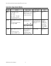
FryerComponentsOperation
The SG and SSH fryer components function in specific order of operation. Knowing and understanding the
sequence of fryer and components operation enables you to diagnose equipment failure more accurately.
HeatingSystem
The unit is connected to line voltage:
If Fuse F1 on the relay board is good:
The A.C. indicator is illuminated.
The controller is supplied with 24 VAC.
With the drain valve handle closed, the proximity switch supplies 24 VAC to the drain valve interlock
(DVI) input at the controller.
24 VAC is at the Side On (SO). relay COM contact.
The controller is turned ON:
The SO indicator on the relay board is illuminated.
The SO relay is energized, closing the circuit.
With the roll out switch and hi-limit in the closed position, the ignition module receives 24VAC at
terminal 6 (24 VAC).
The ignition module:
Sends 24 VAC from terminal 3(PV) to the PV terminal on the gas valve.
Sends the igniter 15kv to spark.
Senses the flame once the pilot has lit and it sends 24 VAC at terminal 1(MV) and puts 24 VAC at the
Heat Demand (HD) relay COM contact on the relay board. The HD relay on the relay board interrupts the
24 VAC supply to the gas valve until the controller calls for heat.
NOTE: When the controller is on, the pilot should always remain lit.
The controller calls for heat:
The HD indicator on the relay board is illuminated.
The HD relay is energized, closing the circuit sending 24 VAC to the MV terminal on the gas valve.
The computer is supplied with a 24 VAC heat feedback (HFB) signal.