


PitcoSolsticeandSolsticeSupremeHighEfficiencyGasFryers
SG/SSHSeriesServiceManual 81
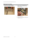
DrainValveandReturnValveSwitches
These switches are a magnetically operated proximity switches. When the drain valve handle is moved to the
open position, the actuator moves away from the switch causing the switch to open. When the drain valve is
closed, the switch closes.
Opening the RED return valve handle closes the proximity switch causing the “pump on” relay to be energized;
the pump begins to pump. Closing the return valve handle opens the proximity switch causing the relay to de-
energize and the pump to stop pumping. These switches can be checked with a Ω meter. When the switch is
closed, there should be continuity. The normal gap between the actuator and the sensor switch on the valve handle
is 1/8 inch to 1/4 inch (3 mm to 6 mm).
Transformer
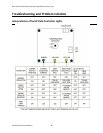
The transformer is a multiple AC input voltage and 24 VAC output voltage. It can be checked by reading the
input and output voltages. A quick check for 24 VAC is done at the relay board behind the front panel. The AC
indicator is illuminated if the F1 fuse is good and the board is receiving 24 VAC.
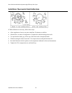
IgnitionModule
With a 24 VAC input at pin #6, the ignition module has a 24 VAC output from terminal 3(PV) and the igniter
sparks until the module senses the pilot flame or for approximately 90 seconds at which time the module locks
out, whichever occurs first. When the module has proven the pilot flame, it has a 24 VAC output at terminal
1(MV) and put 24 VAC to pin 2 at connection J/P32 on the relay board. The relay board interrupts the 24 VAC to
the gas valve until the controller calls for heat.
NOTE: When the controller is on, the pilot should always remain lit.