


PitcoSolsticeandSolsticeSupremeHighEfficiencyGasFryers
SG/SSHSeriesServiceManual 83
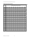
DigitalSolidStateControl
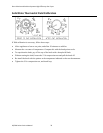
NOTE: All controller test points are at connector P/J1 (closest connector to the controller).
With 24 VAC supplied to pin #1(24VAC supply) and pin # 5(24VAC input from DVI), the display reads “OFF”.
With the controller turned on, there is a 24 VDC output at pin #9 (side on).
When the controller calls for heat, the display reads “HEAt”, there is a 24 VDC output at pin #8 (HD) and a 24
VAC input at pin #6 (HFB). If the controller does not receive the 24 VAC input at pin #6 in approximately 90
seconds, the controller displays “HEAt” “FAIL”. This indicates a break in the HD or HFB circuit.
To correct, do the following:
1. Check the hi-limit switch. Is it open or tripped?
2. Check the ignition module (sensing pilot flame, locked out, 24 VAC at MV terminal).
3. Check the HD relay on the relay board. Is the HD relay energized continuity through COM and NO contacts?
If display reads “Prob”, Ω test the temperature probe. Check the wires and connectors between the probe and
controller for continuity.
If display reads “Prob” “HI”, Ω test the temperature probe, and the wires and connectors between the probe
and controller for a short.
If display reads “drn” “tUrn” “oFF”, verify that the drain valve is closed, check the proximity switch on the
drain valve.
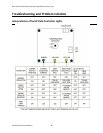
PrimarySolidStateControl
NOTE: All controller test points are at connector P/J3 (the 12 pin connector at the controller).
24 VAC is supplied to the controller at pin #1(24VAC supply) and pin #5 (24 VAC input from DVI).
With the controller turned on, there is a 24 VDC output at pin #9 (SO) and the green indicator is illuminated.
When the controller calls for heat, there is a 24 VDC output at pin #8 (HD), the yellow indicator on the left is
illuminated, and there is a 24 VAC input at pin #6 (HFB).
When the controller receives the 24 VAC input at pin #6, the yellow indicator on the right is illuminated. If the
controller does not receive the 24 VAC input at pin #6, the indicator is not illuminated. This indicates a break in
the HD or HFB circuit.
To correct, do the following:
1. Check the hi-limit switch. Is it open or tripped?
2. Check the ignition module (sensing pilot flame, locked out, 24 VAC at MV terminal).
3. Check the HD relay on the relay board. Is the HD relay energized continuity through COM and NO contacts?
If the green and yellow indicators on the left are illuminated and then shut off when the controller is turned
on, this indicates an open or shorted probe or wires in between the probe and the controller.