INTEGRATING THE EF2241 INTO YOUR SYSTEM
© Polycom, Inc. 19 VORTEX EF2241 Reference Manual
If far end audio and program audio sources are on several Vortex
devices.
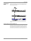
1. Bus each far end audio and program audio source to each device. Do this by
assigning each signal input to either the W, X, Y or Z bus.
2. Assign an echo canceller reference on each device that will include all far end
audio and program audio sources.
C
ONFIGURE
THE
A
UTOMATIC
M
ICROPHONE
M
IXER
The EF2241 contains two independent automatic microphone mixers. Each input
may be assigned to automatic mixer 1, automatic mixer 2, or neither (but not both).
Assign all microphones to the same automixer when using all microphones in the
same room but in different zones, so that a person does not activate microphones in
two different zones (which they would tend to do if each zone had its own automatic
mixer). Use both automatic mixers when the EF2241 is split to operate independently
between two rooms. One automatic mixer is used in each room. The advantage of
having two independent automatic mixers is that when used in two rooms, micro-
phone signals in one room do not affect the gating behavior of microphones in the
other room. Set an input channel to use neither automatic mixer if an input is not
actually a microphone, but is a program audio input. For instance, if you only have 6
microphones and you have an extra stereo program audio source that you want auto-
matic gain control (AGC) on and/or noise cancel, you could set its channels to be on
neither automatic mixer.
If you have a PC, use the Conference Composer software (See the Conference Com-
poser User Guide) to set the automixer parameters. If you would like to set automixer
parameters using the LCD menus, see “Automixer Menu” on page 31 for instructions
on setting automixer parameters.
Automixer
Parameters
The following parameters configure how the EF2241 automatic microphone mixer
operates. Parameters include the following: Decay Time, Hold Time, Camera Gating
Threshold, Chairman Mode, Chairman Mic, Last Mic On Mode, Last Mic Number,
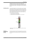
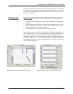
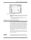
Figure 12. Matrix page of linked devices


