


THE EF BUS
© Polycom, Inc. 25 VORTEX EF2241 Reference Manual
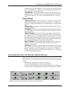
EF Bus Reference. In a system with multiple devices, if all devices need the
same echo canceller reference, one device should be designated to put its echo cancel-
ler reference (either Ref 1 or Ref 2) on the EF bus to be used as the EF Bus Reference.
All other devices
may use the EF bus reference as the reference for their echo cancel-
lers, or they can use their own internal references. The references may include a mix
of any input, with crosspoint gains, including W, X, Y, and Z busses.
NOM Bus. The W, X, Y, and Z busses on the EF Bus contain NOM information.
See “NOM Active” on page 31 for more information on how NOM attenuation is
applied.
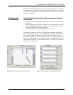
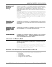
4. Configure Your
Echo Canceller
Reference
Review what inputs need to be included in your echo canceller reference — See
“Build Your Echo Canceller Reference” on page 17. Remember that each micro-
phone needs to have an echo canceller reference. If all microphones are in the same
room and use the same reference, configure the echo canceller reference on one Vor-
tex device and assign it to the EF Bus as the EF Bus Reference. Only one Vortex
device out of multiple units linked together can put an echo canceller reference on the
EF Bus. For each additional unit, assign the echo canceller reference to use the EF
Bus Reference.
For systems with more than one room, you will need to use the W, X, Y, or Z sub-
busses to share the echo canceller reference in your additional rooms if the EF Bus
Reference has already been assigned to the EF Bus.
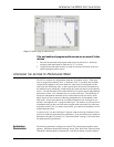
P
RESETS
After configuring your Vortex device, save your settings to a User Preset (PRESETS
16-47). Also, set the P
OWER ON PRESET to the User Preset you have saved to. The
P
OWER ON PRESET determines how the unit is configured upon power up.
If you have multiple Vortex devices in your system, save to a User Preset on each unit
and set the P
OWER ON PRESET accordingly.
O
THER
EF2241 F
EATURES
For information on Macros, Logic Inputs, Logic Outputs, Input Filters and Output
Filters, please refer to the Conference Composer User Guide.
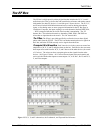
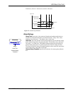
Note. The EF Bus must be connected so that the EF BUS OUT of one
Vortex device is connected to the EF B
US IN of another Vortex
device. Connecting EF B
US IN to another EF BUS IN (or EF BUS
O
UT to EF BUS OUT) will not work. See“Connector Pinouts”
on page 51 for pinout of Cat 5 cable.