


13
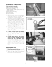
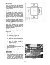
The clamping cylinders can also be adjusted
laterally for better support of workpieces with
differing widths. Simply loosen the locking
handle (Figure 11) and slide the clamping
cylinder to position. Re-tighten locking handle.
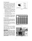
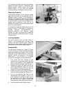
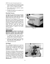
Clamping Pressure
The pressure exerted by the cylinder clamps
against the workpiece can be adjusted at the air
regulator, shown in Figure 12. The hardness or
softness of the wood will determine the amount
of clamping pressure desired. Enough pressure
should be used to prevent the workpiece from
slipping during operations. Forty (40) psi is
suitable for clamping most wood; going above
that is not recommended.
To change the clamping pressure, pull up on the
knob (A, Figure 12) and rotate it; clockwise to
increase pressure, counterclockwise to
decrease pressure. The attached needle
indicator (B, Figure 12) shows the air pressure.
Lock the setting by pushing the knob (A, Figure
12) back down.
Locking Handles
All locking handles, such as those shown in
Figure 11, can be rotated out of the way if they
interfere with other machine parts. Simply lift
straight out on the locking handle and rotate it,
then release, making sure it seats properly.
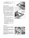
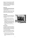
Template Bar
The four-sided template bar, shown in Figure
14, will allow you to create “half-blind” dovetails,
where the dovetails are visible on only one side
of the joint. It will create dovetails in one of four
different “pitches” or centerlines. The available
pitches are 1”, 1-1/2”, 2” and 2-1/2”. To change
the pitch of a dovetail cut, proceed as follows:
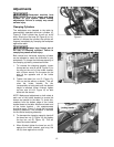
1. First notice how the notches on the
template bar are grouped toward the right
side of the machine. The template bar
should always be oriented in this fashion.
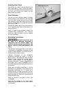
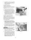
2. Release one end of the spring on the left
side of the headstock (Figure 13) and pull
the headstock forward until the tracer pin
(Figure 14) is clear of the template bar.
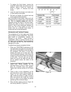
3. Loosen and remove the locking handles on
each end of the template bar (Figure 15).
4. Pull out the template bar, flip it to the
desired side, then reinstall it. NOTE: The
pitch dimension is inscribed on each side of
the template bar. The side of the template
bar that you have chosen should face
downward when mounted on the machine.
5. Insert and tighten both locking handles.
Figure 12
Figure 13
Figure 14