


31
WARNING SERVICING TO BE CARRIED OUT ONLY BY AN AUTHORISED PERSON
Disconnect from electricity and gas before servicing. Check appliance is safe when you have finished.
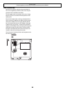
18. To Change Tall Oven Door Magnetic Latch
Remove the control panel (see 1).
Remove the plinth (3 screws) and the central vertical
cover (5 screws). Prize the retaining clip off the magnet
unit. Fit new unit and retaining clip.
Reassemble in reverse order.
Check correct door operation.
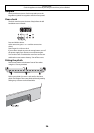
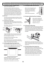
19. To Remove Grill Element.
Disconnect from electricity supply.
Remove grill pan from grill chamber. From inside grill
compartment remove enamelled front shield from
grill roof, 2 screws and washers. Remove 2 screws
and washers securing the grill element front support.
Remove the screws from the grill elements.
Lift elements out carefully, disconnect the leads from
the element terminals noting their position. If it is not
possible to disconnect the leads in this way, pull cooker
forward to gain access to the rear, remove screws
securing the electric cover to the back sheet and remove
cover and disconnect the terminals from the rear.
Fit new elements, reassemble in reverse order. Check
operation of grill.
18. To Remove an Oven Inner Back.
Open the oven door and remove the screws and washers
securing the inner back to the back of the oven.
Carefully lift away the inner back. Reassemble in reverse
order making sure that the 4 screws and washers are
fully tightened.
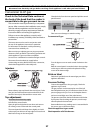
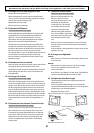
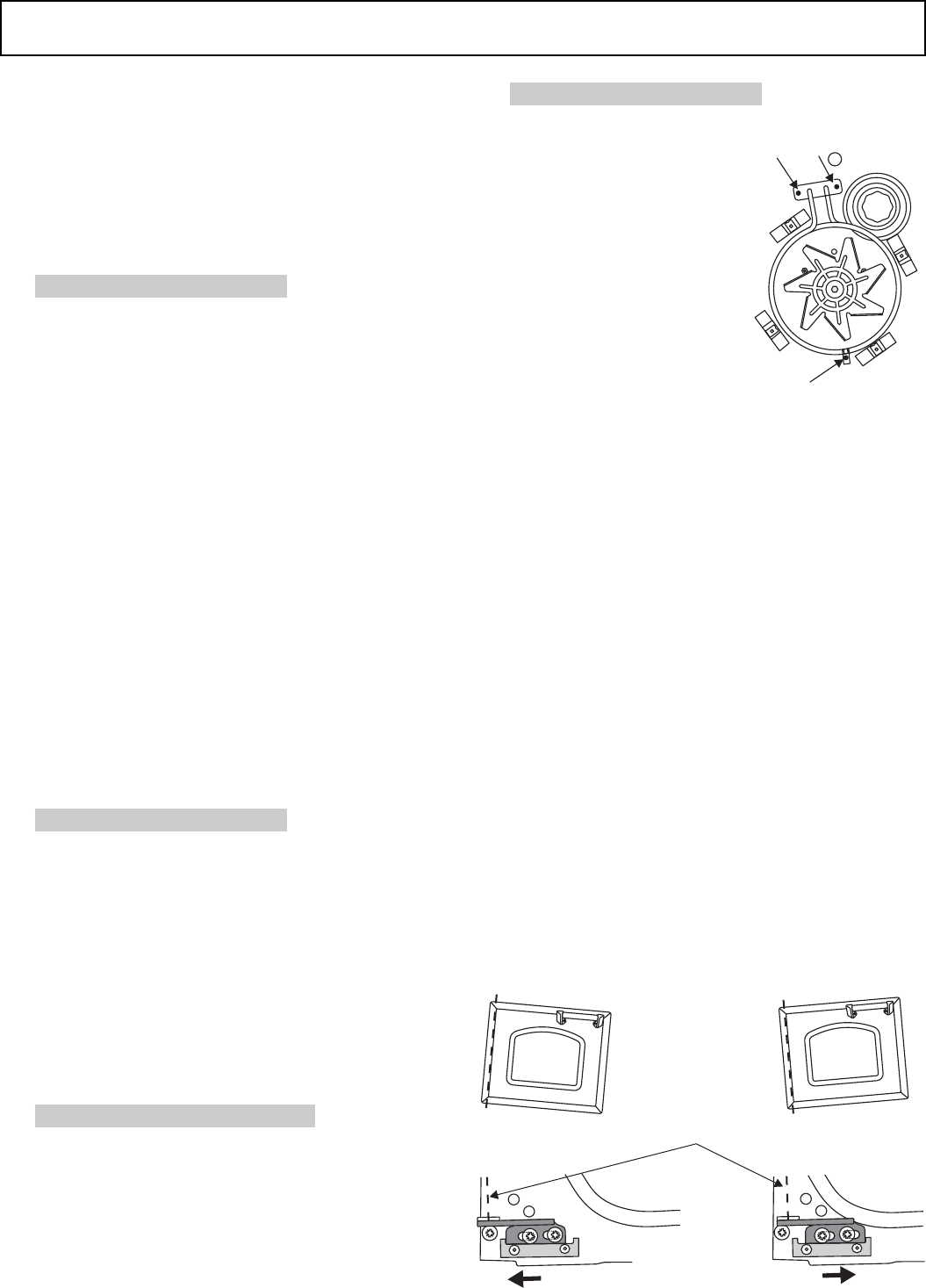
19. To Change Fan in Oven.
Disconnect from electricity supply.
Pull cooker forward to gain access to the rear. Remove
screws securing the electric cover to the back sheet and
remove cover. Disconnect the 3 terminals connected to
the fan noting their position. Remove oven inner back
(see 18). Hold the fan blade and remove the centre nut
(left hand thread) 2 brass washers, fan blade and Circlip.
Unscrew fan retaining nuts and washers (3 off each) and
lift the fan away from the rear of the cooker. Fit new fan
and reassemble in reverse order. Check operation of
oven.
20 To Remove an Oven element Thermal Cut-Out.
Disconnect from the electricity supply.
Pull the cooker for ward to gain access to the cover
box. Undo the cover screws and lift clear. The cutout
is located on the earth plate be side the oven element
con nec tions. Disconnect the cutout wir ing. Undo the
fi xings that secure the cutout to the earth plate and
re move. Fit re place ment control and re-as sem ble in
reverse order.
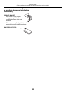
21. To Remove Oven Element.
Disconnect from electricity supply.
Remove oven inner back (see 18).
Remove 2 screws from the
top of the element and 1 from
the bottom of the element
in side the oven. Lift element
out carefully, disconnect the
terminals connected to the
element noting their positions.
If it is not possible to disconnect
the leads in this way, pull cooker
forward to gain access to the
rear.
Remove screws securing the electric cover to the back
sheet and remove cover and disconnect the terminals
from the rear.
Fit new element, and reassemble in reverse order. Check
operation of oven.
22. To change oven light bulb.
LH Oven
Remove the oven furniture and side linings. Remove the
oven rear liner.
RH Oven
Remove the oven inner back (see 18). The oven light
cover is now accessible. Unscrew the cover.
Unscrew the bulb.
Fit an Edison screw fi tting 15w 240v lamp, FOR OVENS. It
must be a special bulb, heat resistant to 300°C.
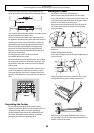
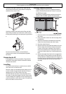
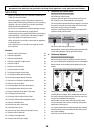
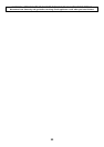
23 To Adjust the Oven Door Angle
The door bottom hinge can be adjusted to alter the
angle of the door.
Loosen the bottom hinge fi xing screws and use the
notch and a fl at bladed screwdriver to move the position
of the hinge to set the hinge position.
Retighten the hinge screws.
Eff ect of hinge adjustment – exaggerated for clarity
Centre line of hinge pin
Oven door omitted for clarity