


21
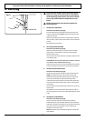
clockwise to raise the cooker and anticlockwise to lower.
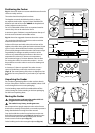
When you are satisfied with the height and level, raise the
front of the cooker by one turn of the front roller adjuster.
Screw down the front feet to meet the floor. Screw the front
roller adjuster anticlockwise to raise the front roller so that
the front of the cooker is supported on the feet, not the front
roller, to prevent accidental movement of the cooker.
Leave the levelling tool on the adjuster with the handle of the
tool facing the rear of the cooker, so that the customer can
use it if they wish to move the cooker.
Replace the drawer by locating it on the side runners and
pushing in.
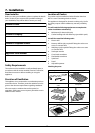
Electrical Connection
The cooker must be installed by a qualified electrician, in
accordance with all relevant British Standards/Codes of
Practice (in particular BS 7671), or with the relevant national
and local regulations.
WARNING: THE APPLIANCE MUST BE EARTHED.
Note: The cooker must be connected to the correct electrical
supply as stated on the voltage label on the cooker, through
a suitable cooker control unit incorporating a double pole
switch, having a contact separation of at least 3mm in all
poles.
The cooker must not be connected to an ordinary
domestic power point.
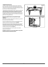
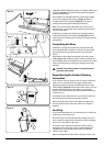
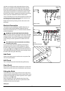
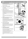
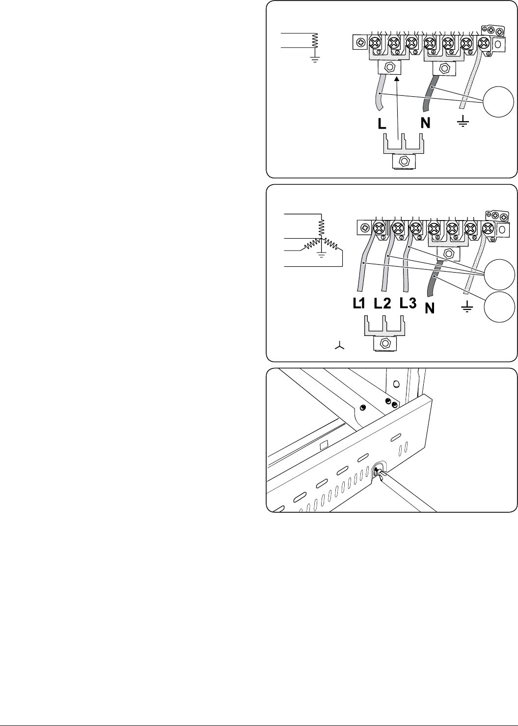
Access to the mains terminal is gained by removing the
electrical terminal cover box on the back panel. Connect
the mains cable to the correct terminals for your electrical
supply type (Fig.7-11 and Fig.7-12). Check that the links are
correctly fitted and that the terminal screws are tight. Secure
the mains cable using the cable clamp.
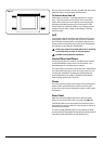
Hob Check
Check each cooking zone in turn. Be sure to use pans of the
correct size and material.
Grill Check
Turn on the grill control and check that the grill heats up.
Oven Check
Set the clock as described earlier, and then turn on the ovens.
Check the oven fans start to turn and that the ovens heat up.
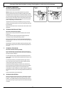
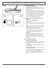
Fitting the Plinth
Loosen the three screws along the front bottom edge of the
cooker. Hook the central keyhole over the central screw. Twist
and fit each end keyhole over their respective screws. Tighten
the fixing screws (Fig.7-13).
Please complete your contact details in the front of this
section. Please inform the user how to operate the cooker
and hand over the instruction pack.
Thank you.
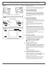
ArtNo.130-0010 Electrical connections single-phase
ArtNo.130-0010 Electrical connections 3-phase
Fig.7-11
Fig.7-12
ArtNo.000-0006 - Securing the 110 plinth
Fig.7-13