


27
Key
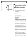
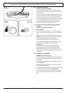
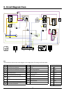
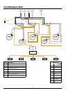
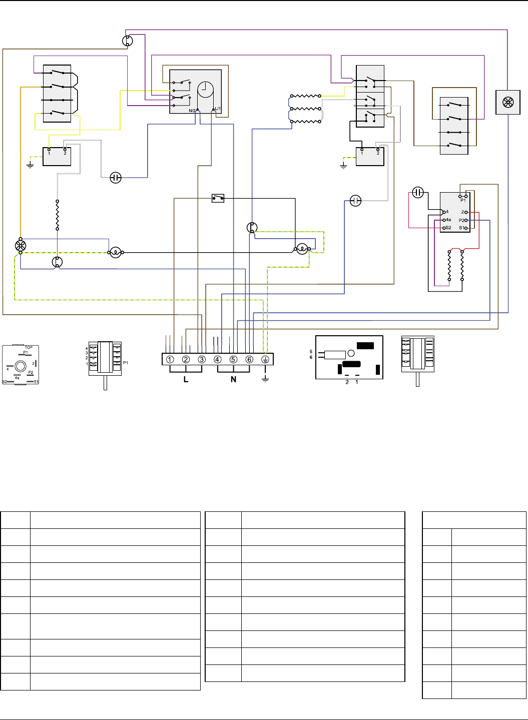
The connections shown in the circuit diagram are for single-phase. The ratings are for 230V 50Hz.
9. Circuit Diagram: Oven
ArtNo.080-0029 110 induction (oven) circuit diagram
�
Code Description
A1 Right-hand oven thermostat
A2 Right-hand oven thermostat front switch
A3 Right-hand oven fan element
A4 Right-hand oven fan
B1 Left-hand zoned oven thermostat
B2
Left-hand zoned oven thermostat front
switch
B3 Zoned oven browning element (inner pair)
B4 Zoned oven top element (outer pair)
B5 Zoned oven base element
Code Description
C Clock
D1 Grill energy regulator
D2 Grill elements
D3 Grill front switch
F Cooling fan
G1 Oven light switch
G2 Oven light
H Thermal cut-out
J Neon
DocNo.095-0002 - Circuit diagram - 110 Induction
Colour Code
b Blue
br Brown
bk Black
or Orange
r Red
v Violet
w White
y Yellow
g/y Green/yellow
gr Grey