


Version 4 27 Feb 08
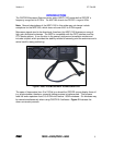
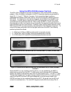
Microwave Transmission Considerations for the MDC
There are important principles and considerations to understand when dealing with
microwave frequency radiators.
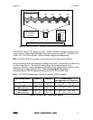
• As the frequency increases, the penetration of RF signals through building materials,
foliage, etc. decreases rapidly. Therefore, microwave signals are considered to be a
line-of-sight (LOS) communication link. If you locate a microwave surveillance device,
the receiving station will be in the direction of the transmission antenna.
• Directional properties of microwave transmissions may be leveraged by the use of
high gain, directional antennas to create an efficient point-to-point RF link. In addition,
the short wavelengths of microwave frequencies allow for decreased dimensions of
such antennas. These techniques result in a signal that is beamed from one location
to another with very little energy wasted in unintended directions, and in turn makes
the RF energy more elusive in it's detection.
• Reflections from metal structures in a building can greatly complicate the location and
detection process. Furthermore, these reflections tend to de-polarize the transmitted
signals rather quickly. The MDC antennas are linearly polarized, and some customers
have had concerns that the polarization effect of the MDC antennas could cause the
user to overlook a transmitter due to an incorrect polarization effect. Rotating the
antenna 90 degrees along the LOS axis can minimize this effect. However, our
experience and testing indicate that this is not a problem because of the reflective
nature of the metal structures in a normal building environment.
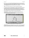
Sweep operations:
The facility you are trying to protect should be considered in
relationship with its surroundings. Any window, or external opening should be considered
a possible LOS portal for microwave radiation. Nearby buildings are potential locations for
receivers.
• Begin any sweep for microwave radiators outside the facility.
• Align the MDC in a LOS path between surrounding buildings and windows or
openings.
• Direct the MDC antennas towards your facility.
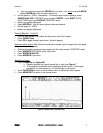
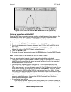
• Operate the OSCOR in peak display mode (traces) for a specific time.
• If devices/signals are detected, note the area of the facility where the signals
originated. Signal strength will be greatest when directional MDC antennas are
aligned along an LOS path and the antenna’s polarity matches the transmitter.
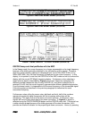
• If devices/signals are detected and determined to not be continuous wave signals, run
traces again and again for shorter and shorter times. In this way you can determine
the time between transmissions. This methodology is crucial for detecting devices
using burst or packet transmitters.
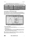
• Sweep inside the facility in the areas where signals originated.
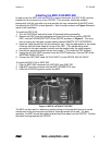
• Once an area of a room is determined to be the transmission source, the MDC may be
used as a probe to locate the transmitter.
Because of the principles above, it is important to understand that to properly use the
MDC, it is necessary to point the MDC in all directions of possible concern. It is advisable
to move the MDC to different locations in the room. It has been suggested that because
of the microwave reflections, it may be possible to completely cover a room by pointing
the MDC directly at the ceiling. The concept is that due to the metal in most ceiling
structures, there would be enough reflective effect to detect a transmitter from any
location in the room. This method has some merits, but it is impossible to predict how
reliable that it would be in all situations. Therefore, this method should only be used when
REI MDC-2100/MDC-900 12